page 2 – 47
2001 / Jul 01
H A R D W A R E
Hook-Ups
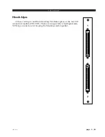
All user wiring to and from OAN-2001 Card takes place at the rear I/O
connector module (ONI-2001). CAT5 or multi-mode optical fiber Audio
Network connections to companion OAN cards are made via RJ-45 or SC type
optical connectors. There are also two female DB-9 serial port connectors for
use as RS-485/RS232 communication links to Wheatstone consoles and XY
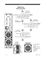
controllers. Pinout drawing on page 2-49 shows all wiring connections at a
glance.
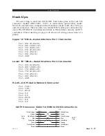
Upper “A” DB-9—Serial Interface Port 1 Connector
Pin 3 – RX1 HI (RS-485)
Pin 8 – RX1 LO (RS-485)
Pin 1 – TX1 HI (RS-485)
Pin 6 – TX1 LO (RS-485)
Pin 2 – TX1 (RS-232)
Pin 7 – RX1 (RS-232)
Pin 5 - GND
Lower “B” DB-9—Serial Interface Port 2 Connector
Pin 3 – RX2 HI (RS-485)
Pin 8 – RX2 LO (RS-485)
Pin 1 – TX2 HI (RS-485)
Pin 6 – TX2 LO (RS-485)
Pin 2 – TX2 (RS-232)
Pin 7 – RX2 (RS-232)
Pin 5 - GND
RJ-45—CAT5 Audio Network Connector
Pin 1 – TXD +
Pin 2 – TXD -
Pin 3 – RXD +
Pin 4 – N/C
Pin 5 – N/C
Pin 6 – RXD -
Pin 7 – N/C
Pin 8 – N/C
CAT5 Crossover Cable for OAN to OAN Connections
1
2
3
4
TXD +
TXD -
RXD +
RXD -
PIN
1
2
3
4
PIN
RJ-45
Plug
RJ-45
Plug
White/Orange
5
6
7
8
N/C
N/C
5
6
7
8
Orange
White/Green
Blue
White/Blue
Green
White/Brown
Brown
White/Green
Green
White/Orange
Blue
White/Blue
Orange
White/Brown
Brown
N/C
N/C
RXD +
RXD -
TXD +
TXD -
N/C
N/C
N/C
N/C

