C O N T R O L P A N E L
page 3 – 15
D-9 / Oct 2003
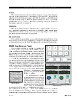
EQ Status
Indicator
password. Default passwords, which may be changed in XPoint, are
“1234” for Admin, “2222” for User, and “0000” for Guest. After dialing
up the first character of the password, press TAKE. Then dial up the second
digit. Continue this procedure until the four characters have been entered.
Upon pressing TAKE after entering the fourth character, the display will
read “Okay...” if you were successful and “Sorry...” if you were not. When
finished, turn PREVIEW SCROLL until the display reads “<<Exit” and
press TAKE to finish the mode select operation.
The ARM button lights as you select the mode that the surface is
currently in. If you press TAKE when displaying the current mode, the
display will switch to “Okay...” and you will not need to enter the
password. If you stop partway through the procedure, the mode selection
process will time out after about 15 seconds.
Once a given control mode is selected for a surface, that setting will
persist through a power cycle or surface reset.
EQ Section
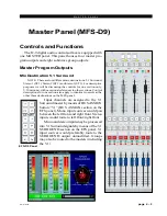
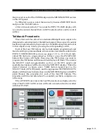
The EQ section consist of a bank of
knobs and various associated switches.
The EQ system consists of a four-band
parametric EQ with low band and high
band PEAK/SHELF switching, plus vari-
able frequency high and low pass filters.
As any of the controls are adjusted, a real
time graphic display is presented on the
LCD monitor panel showing the resulting
frequency response curves.
To access EQ on individual input chan-
nels, press the appropriate channel’s SET
button and make the desired adjustments
in the EQ Section. To actually place the
adjusted EQ in the signal chain, press the
EQ IN button. The input channel’s EQ
button will light, and its LCD display will
show “EQ”. Either the input channel EQ
switch or the master EQ switch on the EFS
panel can be used to engaged/disengaged
the EQ functions on a channel.
High-Pass Filter
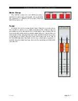
This is a 24dB/octave variable high-pass filter with Butterworth
characteristics, tunable between 16.1Hz and 500Hz, and with a separate in/
out switch (“HPF” switch). The relatively high order of filter is necessary
to allow definite and decisive removal of unwanted low-frequency arti-
facts (air-conditioning rumble, line hum, traffic or footstep impacts) with
minimal effect on the required program.
Note: Butterworth Filters
typically yield excellent
flatness, no ripple in the
pass band and a rounded
amplitude response near
the cutoff frequency.
D-9 / Dec 2004
Summary of Contents for D-9
Page 63: ...D 9 May 2005 page 7 2 ...
Page 64: ...D 9 May 2005 page 7 3 ...
Page 65: ...D 9 May 2005 page 7 4 ...
Page 66: ...D 9 May 2005 page 7 5 ...
Page 67: ...page 7 6 D 9 May 2005 ...
Page 68: ...D 9 May 2005 page 7 7 ...
Page 69: ...page 7 8 IP 9 4 Inputs Panel Switch Card Load Sheet D 9 May 2005 ...
Page 70: ...page 7 9 D 9 Oct 2003 ...
Page 71: ...page 7 2 D 9 Oct 2003 S C H E M A T I C D R A W I N G S IQ 9 IQ Card Load Sheet page 7 10 ...
Page 72: ...page 7 11 D 9 Oct 2003 ...
Page 73: ...page 7 12 D 9 Oct 2003 ...
Page 74: ...page 7 13 D 9 Oct 2003 ...
Page 75: ...page 7 14 D 9 Oct 2003 ...
Page 76: ...page 7 15 D 9 Oct 2003 ...
Page 77: ...page 7 16 MN 9 Control Panel Switch Card Load Sheet D 9 Oct 2003 ...
Page 78: ...D 9 May 2005 page 7 17 ...
Page 79: ...D 9 May 2005 page 7 18 ...
Page 80: ...page 7 19 MFS 9 4 Master Panel Switch Card Load Sheet D 9 May 2005 ...
Page 84: ...D 9 Oct 2003 page 7 23 ...
Page 85: ...D 9 Oct 2003 page 7 24 ...
Page 86: ...D 9 Oct 2003 page 7 25 ...
Page 87: ...page 7 26 DCM 9 DCM Panel Switch Card Load Sheet D 9 Oct 2003 ...
Page 95: ...page 7 34 HC 9 Host Controller Card Load Sheet D 9 Apr 2008 ...
Page 96: ...page 7 35 D 9 Oct 2003 ...
Page 97: ...page 7 36 BP 9 Back Plane Card Load Sheet D 9 Oct 2003 ...
Page 98: ...page 7 37 D 9 Oct 2003 ...
Page 100: ...D 9 Oct 2003 page 7 39 ...
Page 102: ...D 9 Oct 2003 page 7 41 ...
Page 104: ...page 7 43 D 9 Oct 2003 ...
Page 106: ...page 7 45 D 9 Oct 2003 ...

