M A S T E R P A N E L
page 4 – 5
D-9 / Oct 2003
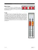
Submixes (Groups) Output
Generally the 8 audio submixes would operate in stereo
mode. They may be mixed to two duplicate mono channels
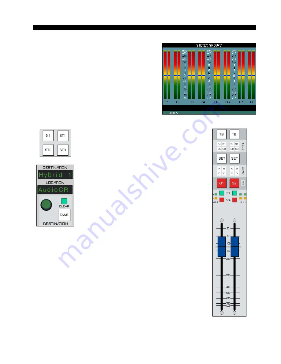
by means of the channel SET button and mode buttons in
the MODE section of the EFS panel. The current mode will
be shown by the LED indicators in the MODE buttons.
TB
Pressing the TB button will allow the announcer’s
mic to talk directly to the group output.
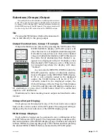
Output Destinations, Group 1 Example
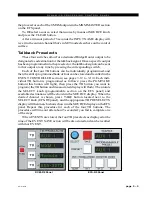
Output destinations are selected by pressing the SET button. The
DESTINATION display (EFS-D9 panel) will
show the most recent output destination assigned.
It should be noted, however, that a mix channel
can go to multiple destinations, and for this reason
the entire list of destinations that channel is as-
signed to is displayed in the LCD display when
that channel’s SET button is active. If the mix is
not assigned anywhere the display will show
“NoDest”.
As you rotate the DESTINATION knob in the
EFS-D9 panel the names of allowable destina-
tions will appear in the DESTINATION display.
If G1 is not currently routed to the displayed
output, the TAKE button will be lit; if G1 is
currently routed to the displayed output, the
CLEAR button will be lit. Press the TAKE button
when lit to add the currently displayed output as a
G1 destination, or press the CLEAR button when lit to delete that
output as a G1 destination.
Destinations for the remaining master outputs are handled in a like
manner.
Groups Output Display
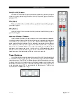
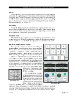
Each group can be assigned to any of the four main stereo output
buses in the center section of the EFS panel. The assigned setting is
displayed by the four indicators of the MSTR display group.
DCM Group Displays
Each submix channel can be assigned to any combination of the
four DCM masters (EFS panel). The assigned setting is displayed by
the four indicators of the DCMS display group. Channels are assigned
to these DCMs by pressing the group’s SET button and then pressing
the desired DCM ASSIGN button, located in the EFS-D9 panel.
EFS-D9 Panel
Summary of Contents for D-9
Page 63: ...D 9 May 2005 page 7 2 ...
Page 64: ...D 9 May 2005 page 7 3 ...
Page 65: ...D 9 May 2005 page 7 4 ...
Page 66: ...D 9 May 2005 page 7 5 ...
Page 67: ...page 7 6 D 9 May 2005 ...
Page 68: ...D 9 May 2005 page 7 7 ...
Page 69: ...page 7 8 IP 9 4 Inputs Panel Switch Card Load Sheet D 9 May 2005 ...
Page 70: ...page 7 9 D 9 Oct 2003 ...
Page 71: ...page 7 2 D 9 Oct 2003 S C H E M A T I C D R A W I N G S IQ 9 IQ Card Load Sheet page 7 10 ...
Page 72: ...page 7 11 D 9 Oct 2003 ...
Page 73: ...page 7 12 D 9 Oct 2003 ...
Page 74: ...page 7 13 D 9 Oct 2003 ...
Page 75: ...page 7 14 D 9 Oct 2003 ...
Page 76: ...page 7 15 D 9 Oct 2003 ...
Page 77: ...page 7 16 MN 9 Control Panel Switch Card Load Sheet D 9 Oct 2003 ...
Page 78: ...D 9 May 2005 page 7 17 ...
Page 79: ...D 9 May 2005 page 7 18 ...
Page 80: ...page 7 19 MFS 9 4 Master Panel Switch Card Load Sheet D 9 May 2005 ...
Page 84: ...D 9 Oct 2003 page 7 23 ...
Page 85: ...D 9 Oct 2003 page 7 24 ...
Page 86: ...D 9 Oct 2003 page 7 25 ...
Page 87: ...page 7 26 DCM 9 DCM Panel Switch Card Load Sheet D 9 Oct 2003 ...
Page 95: ...page 7 34 HC 9 Host Controller Card Load Sheet D 9 Apr 2008 ...
Page 96: ...page 7 35 D 9 Oct 2003 ...
Page 97: ...page 7 36 BP 9 Back Plane Card Load Sheet D 9 Oct 2003 ...
Page 98: ...page 7 37 D 9 Oct 2003 ...
Page 100: ...D 9 Oct 2003 page 7 39 ...
Page 102: ...D 9 Oct 2003 page 7 41 ...
Page 104: ...page 7 43 D 9 Oct 2003 ...
Page 106: ...page 7 45 D 9 Oct 2003 ...


