background image

600 Industrial Drive

New Bern, NC 28562

E

6 OF 7

SA

W# 700740

HC-9

84S0193-6

HC-9E PCB

8-6-07

D-9 / Apr 2008

page 7 - 32

1

8

2

7

3

6

4

5

1

8

2

7

3

6

4

5

SA

SA

- SA UR US - Sergey Averin -

DATE

SIZE

REV

CONTRACT NO.

SCALE

SHEET

DRAWN

CHECKED

ISSUED

FSCM NO.

DWG. NO.

D

APPROVALS

D

A

C

B

D

A

C

B

4.99K

R137

N/C

+3.3V

GND

100uF

C73

+2.5V

GND

0.1uF

C151

100uF

C211

0.1uF

C173

VCC

+3.3V

GND

+3.3V

GND

0.01uF

C84

+2.5V

GND

0.01uF

C85

+3.3V

GND

0.01uF

C88

+3.3V

GND

0.01uF

C86

+2.5V

GND

0.01uF

C87

+2.5V

GND

0.01uF

C89

+2.5V

GND

+3.3V

GND

0.01uF

C114

0.01uF

C115

GND

+2.5V

GND

0.01uF

C122

+2.5V

GND

0.01uF

C123

+3.3V

+3.3V

GND

0.01uF

C131

+2.5V

GND

0.01uF

C141

+3.3V

GND

0.01uF

C132

+2.5V

GND

0.01uF

C140

+3.3V

GND

0.01uF

C157

+3.3V

GND

0.01uF

C158

+2.5V

GND

0.01uF

C166

+2.5V

GND

0.01uF

C165

+3.3V

GND

0.01uF

C189

+2.5V

GND

0.01uF

C188

+2.5V

GND

0.01uF

C192

+3.3V

GND

0.01uF

C187

+3.3V

GND

0.01uF

C191

+2.5V

+3.3V

GND

GND

+2.5V

GND

0.01uF

C190

4

3

2

1

SW9

GND

+3.3V

GND

0.01uF

C231

+3.3V

GND

0.01uF

C232

+3.3V

GND

0.01uF

C230

+3.3V

GND

0.01uF

C233

+3.3V

GND

0.01uF

C234

+3.3V

GND

0.01uF

C235

VCC

GND

0.01uF

C242

100

R140

330pF

C224

GND

LT1117

2

1

3

Q6

GND

IN OUT

1uF

C108

1uF

C177

1uF

C83

1uF

C90

1uF

C193

1uF

C186

47uF

C68

47uF

C214

40

39

38

37

36

35

34

33

32

31

30

29

28

27

26

25

24

23

22

21

20

19

18

17

16

15

14

13

12

11

10

9

8

7

6

5

4

3

2

1

CT36

1

2

3

4

5

6

7

8

9

10

11

12

13

14

15

16

17

18

19

20

21

22

23

24

25

26

27

28

29

30

31

32

33

34

35

36

37

38

39

40

CT39

50MHZ

Y1

_

OUT

E/D

74LCX245

11

9

12

8

13

7

14

6

15

5

16

4

17

3

18

2

1

19

U20

__

OE

A0

___

T/R

A7

A6

A5

A4

A3

A2

A1

B0

B7

B6

B5

B4

B3

B2

B1

+3.3V

74LCX245

19

1

2

18

3

17

4

16

5

15

6

14

7

13

8

12

9

11

U21

__

OE

A0

___

T/R

A7

A6

A5

A4

A3

A2

A1

B0

B7

B6

B5

B4

B3

B2

B1

+3.3V

74LCX245

11

9

12

8

13

7

14

6

15

5

16

4

17

3

18

2

1

19

U22

__

OE

A0

___

T/R

A7

A6

A5

A4

A3

A2

A1

B0

B7

B6

B5

B4

B3

B2

B1

+3.3V

74LCX245

19

1

2

18

3

17

4

16

5

15

6

14

7

13

8

12

9

11

U17

__

OE

A0

___

T/R

A7

A6

A5

A4

A3

A2

A1

B0

B7

B6

B5

B4

B3

B2

B1

+3.3V

74LCX245

11

9

12

8

13

7

14

6

15

5

16

4

17

3

18

2

1

19

U18

__

OE

A0

___

T/R

A7

A6

A5

A4

A3

A2

A1

B0

B7

B6

B5

B4

B3

B2

B1

+3.3V

74LCX245

19

1

2

18

3

17

4

16

5

15

6

14

7

13

8

12

9

11

U19

__

OE

A0

___

T/R

A7

A6

A5

A4

A3

A2

A1

B0

B7

B6

B5

B4

B3

B2

B1

+3.3V

6

5

4

3

2

1

CT19

XC2S200

207

206

205

204

203

202

201

200

199

195

194

193

192

191

189

188

187

185

182

181

180

179

178

176

175

174

173

172

168

167

166

165

164

163

162

161

160

159

157

155

154

153

152

151

150

149

148

147

146

142

141

140

139

138

136

135

134

133

132

129

127

126

125

123

122

121

120

119

115

114

113

112

111

110

109

108

107

106

104

102

101

100

99

98

97

96

95

94

90

89

88

87

86

84

83

82

81

80

77

75

74

73

71

70

69

68

67

63

62

61

60

59

58

57

54

52

50

49

48

47

46

45

44

43

42

41

37

36

35

34

33

31

30

29

27

24

23

22

21

20

18

17

16

15

14

10

9

8

7

6

5

4

3

2

U11

I/O

I/O

I/O,V

RE

F

0

I/O,V

RE

F

5

I/O

I/O

I/O

I/O

I/O

I/O

I/O

I/O

I/O

D0,DIN,I/O

D7,I/O

B

U

S

Y

,DOUT

,I/O

INIT

,I/O

____

CS

,I/O

I/O

___

W

R

IT

E

,I/O

I/O

______

I/O

I/O

I/O

I/O

I/O,V

RE

F

1

I/O,V

RE

F

4

I/O

I/O

I/O

I/O

I/O,V

RE

F

1

I/O,V

RE

F

4

I/O

I/O

I/O

I/O

I/O

I/O

I/O

I/O

I/O

I/O

I/O

I/O

I/O,V

RE

F

1

I/O,V

RE

F

4

I/O

I/O

I/O

I/O

I/O

I/O

GC

K

2

,I

GC

K

0

,I

GC

K

3

,I

GC

K

1

,I

I/O

I/O

I/O

I/O

I/O,V

RE

F

0

I/O,V

RE

F

5

I/O

I/O

I/O

I/O

I/O

I/O

I/O

I/O

I/O

I/O

I/O

I/O

I/O,V

RE

F

0

I/O,V

RE

F

5

I/O

I/O

D6,I/O

I/O,VREF3

I/O

I/O

I/O,VREF3

_________

PROGRAM

DONE

TMS

TDI

TDO

I/O

I/O,VREF2

I/O

I/O

I/O,VREF2

D1,I/O
D2,I/O

I/O

I/O

I/O

I/O

I/O,VREF2

D3,I/O

I/O

I/O

I/O,IRDY

I/O,TRDY

I/O

D4,I/O

I/O,VREF3

I/O

I/O

I/O

I/O

D5,I/O

CCLK

TCK

I/O

I/O,VREF6

I/O

I/O

I/O

M2

M1

M0

I/O

I/O

I/O

I/O,VREF7

I/O

I/O

I/O,VREF7

I/O

I/O

I/O

I/O
I/O

I/O

I/O,VREF7

I/O

I/O

I/O

I/O,IRDY

I/O,TRDY

I/O

I/O

I/O,VREF6

I/O

I/O

I/O
I/O

I/O

I/O

I/O,VREF6

I/O

+3.3V

CCLK

DONE

PR

O

M

D

1

INIT

I_GUI_15

O_FB_CKE

O_FB_CLK

O_FB_DQM1

IO_FB_D[8]

IO_FB_D[9]

IO_FB_D[10]

IO_FB_D[11]

IO_FB_D[13]

IO_FB_D[14]

IO_FB_D[12]

IO_FB_D[15]

IO_FB_D[7]

IO_FB_A[6]

IO_FB_A[5]

IO_FB_A[8]

IO_FB_A[7]

IO_FB_A[11]

IO_FB_A[9]

IO_FB_A[4]

IO_FB_BA[0]

AT_FSYNC

AT

_

M

C

L

K

PR

O

M

D

2

VGA_TMS

VGA_TCK

VGA_TDO

VGA_TDI

GND

G_LE

D

[1]

G_LE

D

[0]

G_LE

D

[2]

G_LE

D

[3]

P

OW

E

R

GOOD

D

IPSW_

VS[

3

]

D

IPSW_

VS[

2

]

D

IPSW_

VS[

1

]

D

IPSW_

VS[

0

]

I_SCLK

I_LP

I_GUI_6

I_F

L

M

BP_

M

ET

ER

_

G

DIPSW_VS[0]

DIPSW_VS[1]

DIPSW_VS[2]

DIPSW_VS[3]

50M_CLK

IO_FB_A[2]

IO_FB_A[3]

IO_FB_A[1]

IO_FB_A[0]

IO_FB_A[10]

IO_FB_BA[1]

50M_C

LK

O_F

P

2R

[1]

O_F

P

2R

[2]

O_F

P

2R

[3]

O_F

P

2R

[4]

O_F

P

2R

[5]

O_F

P

2G[1]

O_F

P

2G[2]

O_F

P

2G[3]

O_F

P

2G[4]

O_F

P

2G[5]

O_F

P

2B

[1]

O_FP3R[1]

O_FP3R[2]

O_FP3R[3]

O_FP3R[4]

O_FP3R[5]

O_FP3G[1]
O_FP3G[2]

O_FP3G[3]

O_FP3G[4]

O_FP3G[5]

I_GUI_7

O_FP_ENAB

O_LVDS_CK

I_GUI_1

V

G

A

_2_C

S

_2

I_GUI_0

I_GUI_3

I_GUI_5

I_GUI_9

I_GUI_11

I_GUI_10

I_GUI_8

I_GUI_4

I_GUI_2

O_FB_SP2

O_FB_DQM2

I_DE

I_GUI_16

I_PCLK

I_GUI_17

O_FB_SP1

V

G

A

_2_C

S

_1

C

S

_2_V

GA

_1

C

S

_2_V

GA

_2

IO_FB

_D

[16]

ME

TE

R

_

S

D

[0

]

ME

TE

R

_

S

D

[1

]

O_FP

_E

N

B

_P

W

R

IO_FB

_D

[17]

O_B

K

L_P

W

M

O

_

F

B_

VSYN

C

I_GUI_14

I_GUI_13

I_GUI_12

IO_FB

_D

[6]

IO_FB

_D

[5]

IO_FB

_D

[4]

IO_FB

_D

[3]

IO_FB

_D

[2]

IO_FB

_D

[1]

IO_FB

_D

[0]

O_FB

_C

LK

O_FB_CLK

O_FP_SCLK[0]

O_FP_SCLK[1]

O_FP_SCLK[2]

O_FP_SCLK[3]

O_FP_HSYNC

O_FP3B[1]

O_FP3B[2]

O_FP3B[3]

O_FP3B[4]

O_FP3B[5]

O_FP2B[2]
O_FP2B[3]

O_FP2B[4]

O_FP2B[5]

O_F

P

1R

[1]

O_F

P

1R

[2]

O_F

P

1R

[3]

O_F

P

1R

[4]

O_F

P

1R

[5]

O_F

P

1G[1]

O_F

P

1G[2]

O_F

P

1G[3]

O_F

P

1G[4]

O_F

P

1G[5]

O_F

P

1B

[1]

O_F

P

1B

[2]

O_F

P

1B

[3]

O_F

P

1B

[4]

O_F

P

1B

[5]

GND

I_B_GUI_0

I_B_GUI_2

I_B_GUI_4

I_B_GUI_6

I_B_GUI_8

I_B_GUI_10

I_B_GUI_1

I_B_GUI_3

I_B_GUI_5

I_B_GUI_7

I_B_GUI_9

I_B_GUI_11

I_B_GUI_12

I_B_GUI_14

I_B_GUI_16

I_B_SCLK

I_B_DE

I_B_GUI_13

I_B_GUI_15

I_B_GUI_17

I_B_FLM

I_B_LP

GND

GND

GND

GND

GND

I_A_GUI_0

I_A_GUI_2

I_A_GUI_4

I_A_GUI_6

I_A_GUI_8

I_A_GUI_10

I_A_GUI_1

I_A_GUI_3

I_A_GUI_5

I_A_GUI_7

I_A_GUI_9

I_A_GUI_11

I_A_GUI_12

I_A_GUI_14

I_A_GUI_16

I_A_SCLK

I_A_DE

I_A_GUI_13

I_A_GUI_15

I_A_GUI_17

I_A_FLM

I_A_LP

GND

GND

GND

GND

I_A_GUI_2

I_A_GUI_0

I_A_GUI_14

I_A_GUI_12

I_A_GUI_13

I_A_GUI_16

I_A_GUI_4

I_A_GUI_11

I_A_GUI_9

I_A_GUI_5

I_A_GUI_3

I_A_GUI_6

I_A_FLM

I_A_GUI_1

I_A_GUI_7

I_A_LP

I_A_GUI_8

I_A_GUI_10

I_GUI_2

I_GUI_0

I_GUI_14

I_GUI_12

I_GUI_13

I_GUI_16

I_GUI_4

I_GUI_11

I_GUI_9

I_GUI_5

I_GUI_3

I_GUI_6

I_FLM

I_GUI_1

I_GUI_7

I_LP

I_GUI_8

I_GUI_10

I_GUI_2

I_GUI_0

I_GUI_14

I_GUI_12

I_GUI_13

I_GUI_16

I_GUI_4

I_GUI_11

I_GUI_9

I_GUI_5

I_GUI_3

I_GUI_6

I_FLM

I_GUI_1

I_GUI_7

I_LP

I_GUI_8

I_GUI_10

I_B_GUI_2

I_B_GUI_0

I_B_GUI_14

I_B_GUI_12

I_B_GUI_13

I_B_GUI_16

I_B_GUI_4

I_B_GUI_11

I_B_GUI_9

I_B_GUI_5

I_B_GUI_3

I_B_GUI_6

I_B_FLM

I_B_GUI_1

I_B_GUI_7

I_B_LP

I_B_GUI_10

VGA_TMS

VGA_TDI

VGA_TDO

VGA_TCK

GND

+3.3V

I_B_GUI_8

GND

GND

I_GUI_15

GND

I_A_GUI_15

I_GUI_15

GND

I_B_GUI_15

I_A_DE

I_A_SCLK

I_DE

I_SCLK

I_GUI_17

I_A_GUI_17

I_DE

I_SCLK

I_B_DE

I_B_SCLK

I_B_GUI_17

I_GUI_17

VGA (G)

VGA (G) PC-104

2.5V

Summary of Contents for D-9

Page 1: ...D 9 Digital Control Surface TECHNICAL MANUAL 600 Industrial Drive New Bern North Carolina USA 28562 ...

Page 2: ...tal Control Surface Technical Manual 1st Edition D 9 Digital Control Surface Technical Manual 1st Edition D 9 Digital Control Surface Technical Manual 1st Edition D 9 Digital Control Surface Technical Manual 1st Edition D 9 Digital Control Surface Technical Manual 1st Edition 2003 Wheatstone Corporation D 9 Oct 2003 ...

Page 3: ...nstalled and used in accordance with the instruction manual may cause harmful interference to radio communications Operation of this equipment in a residential area is likely to cause harmful interference in which case the user will be required to correct the interference at his own expense This is a Class A product In a domestic environment this product may cause radio interference in which case ...

Page 4: ...t clean lint free cloth or micro fiber cloth and clean lukewarm water to clean the surface For stubborn dirt and stains use a mild nonabrasive soap and water mixture with the gentle cleaning cloth Use only light pressure when cleaning Avoid rubbing dirt or grit into the surface Turn the cloth often and replace with a clean cloth frequently Dry by blotting gently with a clean dry cloth AVOID using ...

Page 5: ...ure Double Connection to One Pin 1 8 Chapter 2 Input Panel IS D9 Controls and Functions 2 2 Input Sources 2 2 Gain Control 2 3 Phantom Power 2 3 AUX 2 3 Mode Selector Indicator 2 3 Pan Balance Knob 2 3 Bus Minus 2 4 Dynamics and EQ 2 4 Main Bus Assign 2 4 Output Assign Displays 2 4 SET Button 2 5 Page Button 2 5 DCM Displays 2 5 PFL Cue Switch 2 6 AFL Solo Switch 2 6 Channel ON Switches 2 6 Fader ...

Page 6: ... 3 9 To Copy One To All 3 10 Test Section 3 10 Timer Section 3 10 Time of Day Clock 3 11 XY Controller Section 3 11 Selecting Input Channel Sources 3 11 Selecting Output Mix Destinations 3 11 Changing Output Mix Destinations 3 12 Removing Output Mix Destinations 3 12 X Y Set Button 3 12 Event Controller Section 3 11 Storing an Event 3 12 Taking an Event 3 13 Undoing an Event 3 13 Modifying the Cur...

Page 7: ... 5 DCM Group Displays 4 5 ON G1 G8 Switch 4 6 PFL Cue 4 6 AFL Solo 4 6 Submix Group Faders 4 6 Page Buttons 4 6 Chapter 5 Dynamics Processing Control Panel DCM D9 Controls and Functions 5 2 Compressor Limiter 5 2 Dyn In 5 3 Threshold 5 3 Attack 5 3 Ratio 5 4 Release 5 4 Makeup Gain 5 4 MXM Confidence Feed 5 4 Talkback Preselects 5 5 Display Buttons 5 6 Programmable Buttons 5 6 Mute Groups 5 7 Fade...

Page 8: ...erface 6 6 Optical Transceiver 6 6 Connectors Type 6 6 Optical Fiber Cable 6 6 HC 9 Pinouts Drawing 6 7 Chapter 7 Schematic and Load Sheet Drawings IP 9 4 Inputs Panel Switch Card Schematic 7 2 Load Sheet 7 8 IQ 9 IQ Card Schematic 7 9 Load Sheet 7 10 MN 9 Control Panel Switch Card Schematic 7 11 Load Sheet 7 16 MFS 9 Master Panel Switch Card Schematic 7 17 Load Sheet 7 19 IQO 9 Master Panel IQ Ca...

Page 9: ...atic 7 43 Load Sheet 7 44 PWI 5 1 Power Interface Card Schematic 7 45 Load Sheet 7 46 Appendices Appendix 1 Control Surface Clock A 3 Setting the Time A 3 Update Options A 3 Synchronize A 3 Battery Backup A 4 Appendix 2 Options Text File A 6 Introduction A 6 Modifying The Options Text File A 6 A Sample Example From The File A 7 A Second Example A 8 An Example File Complete A 9 Appendix 3 Replaceme...

Page 10: ...al Information Chapter Contents Introduction 1 2 Control Surface Placement 1 3 Power Supply 1 4 Failsafe Dual Redundant Supply 1 5 Energizing 1 5 I O Connections 1 6 The Insulation Displacement Connector System 1 6 Wiring Procedure Double Connection to One Pin 1 8 ...

Page 11: ... It even has programmable talkback buttons Designed to integrate flawlessly with the Wheatstone BRIDGE digital audio network router the D 9 control surface allows you to easily create large or small platform basedsystemsthatareexceptionallyuser friendlyandflexible Wheat stone BRIDGE network cages house all I O ports and engine cards and may be wired in tandem within a single equipment room or inte...

Page 12: ...priate panels from the frame screw the mainframe to the counter top and reinstall the removed panels The three available frame sizes dimensions in inches are shown in the drawings below Do not connect the D 9 control surface to its power supply and do not connect the power supply to the AC power line until instructed to do so D 9 Jan 2006 77 380 18 355 18 780 14 500 10 HOLES D 0 200 USE 8 SCREWS 1...

Page 13: ...o powersupplyconnectorsarelocated at the rear of the control surface in the middle of the meterbridge bot tom pan If you are using one supply connect it to one of the control sur face connectors it doesn t matter which one If you are using the failsafe option connect one end of a power supply cable to either control surface power connector and con nect the other end of the cable to one of the two ...

Page 14: ...e AC mains The control surface sLCDdisplayswillilluminateandindividualmoduleswitches will assume factory default settings Note To de energize the control surface unplug the rackmount power supply s AC cord from the AC mains Never de energize the control surface by disconnecting the cable that connects the control surface and power supply together Once you have verified proper power up unplug the r...

Page 15: ...ections are made via the female DB 15 connector that is mounted next to the ENET A connec tor For all wiring pinout connections refer to Chapter 6 The sketch below shows connector locations The Insulation Displacement Connector System The I O wiring interface system is based on insulation displacement technology A special AMP wiring tool is included with each control surface it is auto indexing an...

Page 16: ... accept wire gauge 22 26 AWG In the event of a wiring error connector pins may easily be removed from the shell with the wire still attached and inserted into the correct position Observe the side of the connector with the metal part down You will see a row of Vees simply press the top of the vee together with a scribe or other sharp instrument this will unlock the pin from the shell and it can be...

Page 17: ... wire to the desired pin as you normally would 2 Note connector pins may easily be removed from the DB 25 shell with the wire still attached Hold the connector with the metal part down and observe its side You will see a row of Vees simply press the top of the selected vee together with a scribe or other sharp instrument this will unlock the pin from the shell allowing it to be removed 3 With the ...

Page 18: ...2 3 Mode Selector Indicator 2 3 Pan Balance Knob 2 3 Bus Minus 2 4 Dynamics and EQ 2 4 Main Bus Assign 2 4 Output Assign Displays 2 4 SET Button 2 5 Page Button 2 5 DCM Displays 2 5 PFL Cue Switch 2 6 AFL Solo Switch 2 6 Channel ON Switches 2 6 Fader 2 6 LCD Display 2 6 Input Level 2 7 Selected Source 2 7 Preset Source 2 7 Channel Status 2 7 Channel Number 2 7 ...

Page 19: ...LCD screen above the channel strip When the desired input source is scrolled into the SOURCEwindow pressingtheTAKEbuttonwillcause that source to be switched to the input of the channel and the source name will be displayed in the SOURCE window of the LCD screen A second source can be loaded into the PRESET window of the LCD screen Scroll the INPUT knob as above until the desired source appears in ...

Page 20: ...p 2 or 4 Once the desired AUX SEND has been selected using these controls theON PREFDR andPREONswitchesandtheencodercan be adjusted for that particular AUX SEND without pressing down the encoder turning it adjusts the level of that channel in the aux send turning it while pressing the knob down pans the channel between the left and right sides of the stereo aux send bus Subsequently the bank selec...

Page 21: ...t outputs A TB switch lets the control surface operator talk back to that individual IFB direct output allowing communications between the operator and the talent receiving that mix A SOLO switch allows the operator to solo monitor the individual channel s IFB feed Dynamics and EQ DYNAMICS DYN and EQ buttons allow dynamics and EQ functions which have been set for that channel on the DCM Chapter 5 ...

Page 22: ...onison Eachaudiochannelcontrolled by a fader is controllable separately via the PAGE button yet both audio channelsareavailablesimultaneously Thatis ifyouhavejustsetthelevel for channel 17 using fader 1 with the PAGE button on turning the PAGE buttonoffswitchescontroltochannel1 butchannel17continuestosound On the top of MASTER panel see Chapter 4 there are page buttons which allow groups of input ...

Page 23: ...atthefaderindicates Thechannel output level will remain at the computer directed value until the fader is moved to a matching level after which the fader will control the level The lit NULL LED indicates which direction to move the fader to regain level control Once the fader has been moved to the matching level the LED will turn off The D 9 control surface can be ordered with optional touch sensi...

Page 24: ...0dB 4dBu analog and 20dBFS digital Selected Source The currently selected source name shows on the LCD display under neath the level bargraph This name is the 8 character name as defined in the Wheatstone Bridge Router configuration Preset Source The currently loaded preset source name shows on the LCD display underneath the currently selected source Once again this 8 character name is as defined ...

Page 25: ...e and Paste Many 3 9 To Copy One To All 3 10 Test Section 3 10 Timer Section 3 10 Time of Day Clock 3 11 XY Controller Section 3 11 Selecting Input Channel Sources 3 11 Selecting Output Mix Destinations 3 11 Changing Output Mix Destinations 3 12 Removing Output Mix Destinations 3 12 X Y Set Button 3 12 Event Controller Section 3 12 Previewing an Event 3 12 Taking an Event 3 13 Undoing an Event 3 1...

Page 26: ...vailable CONTROL ROOM STUDIO 1 STUDIO 2 and HEADPHONE Each monitor has a LEVEL control a SET button a DIM switch a TB button but the CR monitor does not have a TB button and a MIX display that is located on the bottom section of the EFS D9 panel The CR monitor section also contains a mode indicator and two speakers select buttons Monitor sources can be selected several ways Four PRE PRO GRAMMED MO...

Page 27: ... operator s microphone may thus provide a part of the signal that is going out over the air If that signal is the one being monitored with the control room speakers there is the potential for feedback The amplified signal from the control room speakers is picked up by the microphone and reamplified to a new higher level which then is once again picked up by the microphone The signal quickly rises ...

Page 28: ...p in level Actual DIM level is set by the DIM encoder at the top of this panel Note the DIM function also affects the talkback interrupt Note also if the studioismuted talkbackcannotbeheard However ifthestudioisdimmed talkback audio could presumably make it from the studio monitor speakers to the open studio mic TALKBACK TB BUTTON there may be times when the control surface operator wants to talk ...

Page 29: ... on the EFS D9 panel consisting of eight group assign switches and four master assign switches The switches illuminate to indicate the assign status of the input channel or group whose SET switch is currently active Indicator windows on the input or group panels show the assign status for each individual source Bus assignment may be made in any combination and is accomplished by first pressing the...

Page 30: ...l ling the mute function The AFL SOLO master level control and defeat switch are also located on the top section of the EFS panel The AFL SOLO signal is after fader and is normally used to check a mix When an output such as an AUX SEND is SOLOed its post fader signal will appear in the solo output and usually the control room speakers The switched meter array in the master LCD display will show th...

Page 31: ...OLO CUE button is pressed the SOLO CUE level will be temporarily shown in the switched meter display until the SOLO CUE button is deactivated Mode Select Section The mode selector switchbank ST LT RT MONO BLEND and SURR buttons and LT RT knob are located in the center of the Control panel There are six available channel modes STEREO LEFT ONLY RIGHT ONLY MONO BLEND and SURROUND When pressed the swi...

Page 32: ...ding MIX MINUS ASSIGN switch will be lit Pressing a MIX MINUS ASSIGN switch will toggle that input s signal into or out of the corresponding MXM bus DCM Assign To assign a DCM to an input submix or master place the input submix or master channel in SET mode and press any combination of theDCMASSIGNbuttons TheappropriateDCMSdisplayclusteron the inputs IS D9 panel or submixes or masters MFS D9 panel...

Page 33: ... each PAGE if desired There can even be overlap for example you can choose to copy from channels 1 2 and 3 to channels 2 4 and 5 After this copy channels 1 and 3 would not have changed channel 2 would be set as channel 1 had been channel 4 would be set as channel 2 had been and channel 5 would be set as channel 3 had been When selecting channels for the COPY and PASTE sets the order in whichyoupre...

Page 34: ... with ST ID TONES button establishes a STEREO ID tone The test tone destination is chosen by pressing the SET button at the desired destination location and then the ASSIGN button in the test tone section To use any of the test tones press the ON button When it is lit the selected test tone is available when not lit the tones are off Timer Section The control surface timer is provided with an AUTO...

Page 35: ...red source is shown in the SOURCE display pressing the TAKE button will execute the take command on the downstroke and the new input will be shown in the SOURCE display and in the meterbridge LCD display This function operates the same as the SOURCE knob on the input panels To remove the input source from the input channel and leave nothing connected press the CLEAR button The connection will be b...

Page 36: ...ination to be deleted is shown in the DESTINATION display press the CLEAR button X Y SET Button Pressing the X Y SET button allows the source and destination controls to act as a standard X Y type router controller for making connectionsbetweensourcesanddestinationsthatarenotassociatedwith the control surface Event Controller Section This section provides a means for storage and retrieval of contr...

Page 37: ...n the SAVE button In this way the modified event will overwrite the old event setting and be saved with the same name in its place Deleting an Event Rotate the PREVIEW SCROLL encoder until the Event to be deleted is shown in the PROGRAM PREVIEW display Press the Modify button then press the PREVIEW SCROLL knob the display will ask DELETE Press the TAKE button to delete the previously displayed Eve...

Page 38: ... you want to change Once the cursor is at the desired character rotate the ALPHA SCROLL encoder until the desired new character is displayed Once all desired characters have been changed simply press SAVE to save your changes The event is stored with the desired name At any time you can cancel the name edit by pressing the ALPHA SCROLL knob Also if you stop making name changes but fail to press th...

Page 39: ...ed switches The EQ system consists of a four band parametric EQ with low band and high bandPEAK SHELFswitching plusvari able frequency high and low pass filters As any of the controls are adjusted a real time graphic display is presented on the LCDmonitorpanelshowingtheresulting frequency response curves ToaccessEQonindividualinputchan nels press the appropriate channel s SET button and make the d...

Page 40: ... shelving function The composite effect of any EQ adjust ments as well as text describing the equalizer settings are shown on the LCD screen Phase A pair of switches one for left and one for right are provided to cause the reversal of absolute phase of the signal path Function Lock Itisanecessityundersomecircumstancesthatnon technicalpersonnel be prevented from adjusting a control surface s signal...

Page 41: ...on will be canceled When you press a locked control the FUNCTION LOCK button flashestoletyouknowyouhavetriedtoaccessalockedcontrol Tounlock the control press the FUNCTION LOCK button once The locked control is released If you fail to press the FUNCTION LOCK button within about five seconds of pressing the locked control the operation will time out and the control will remain locked D 9 Aug 2004 ...

Page 42: ...urround 4 2 Master Mix Destinations 4 3 Channel Master ON OFF 4 3 Dyn 4 3 EQ 4 3 DCM Master Displays 4 4 PFL Cue 4 4 AFL Solo 4 4 Master Faders 4 4 Submixes Groups Outputs 4 5 TB 4 5 Output Destinations Group 1 Example 4 5 Groups Output Display 4 5 DCM Group Displays 4 5 ON G1 G8 Switch 4 6 PFL Cue 4 6 AFL Solo 4 6 Submix Group Faders 4 6 Page Buttons 4 6 ...

Page 43: ...Surround with occasional references to other sections Control descriptions for one section also apply to identical controls at the other three destinations on the MFS panel Input channels are assigned to the 5 1 Surround master by means of BUS ASSIGN button 5 1 BUS ASSIGN section on the EFS panel Mono input sources would pan between the left front and right front Stereo inputs would route to left ...

Page 44: ... be lit Press the TAKE button when lit to add the currently displayed output as a 5 1 destination or press the CLEAR button when lit to delete that output as a 5 1 destination Destinations for the remaining master outputs are handled in a like manner Channel Master ON OFF The ON switch turns the channel signal ON pressing it again turns the channel signal OFF The switch LED lights to indicate the ...

Page 45: ...ol surface operator monitor the master s post fader signal Master Faders Theselinearcontrolssetthelevelsofthemasterchannels Whenthe control surface has recalled a preset or is under external serial control from an automation system the fader NULL LEDs light to show that the master output level is actually different from what the fader indicates The master output level will remain at the computer d...

Page 46: ...st As you rotate the DESTINATION knob in the EFS D9 panel the names of allowable destina tions will appear in the DESTINATION display If G1 is not currently routed to the displayed output the TAKE button will be lit if G1 is currently routed to the displayed output the CLEAR button will be lit Press the TAKE button when lit to add the currently displayed output as a G1 destination or press the CLE...

Page 47: ...at the master output level is actually different from what the fader indicates The master output level will remain at the computer directed value until the fader is moved to a matching level after which the fader will control the level The lit NULL LED indicates which direction to move the fader to regain level control Once the fader has been moved to the matching level the LED will turn off Page ...

Page 48: ... Processing Control Panel DCM D9 Chapter Contents Controls and Functions 5 2 Compressor Limiter 5 2 Dyn In 5 3 Threshold 5 3 Attack 5 3 Ratio 5 4 Release 5 4 Makeup Gain 5 4 MXM Confidence Feed 5 4 Talkback Preselects 5 5 Display Buttons 5 6 Programmable Buttons 5 6 Mute Groups 5 7 Fader 5 7 ...

Page 49: ...ned to allow smooth inaudible and unobtrusive level control on uneven sources be able to act as a peak limiter for inadvertent overload control enable deep effects if required TheDCM 9panelcompressorsectionisacompoundofmany diverse dynamics elements The level detector is a pseudo RMS averaging type with its own symmetrical in time attack and release characteristic ad justable between 0 1mS and 330...

Page 50: ...nput channel also has its own DYN button to allow engaging these functions directly from the input panel Whenever dynamic functions are engaged the input channel LCD display will show a gain reduction bargraph meter indicating both that the dynam ics functions are active and the amount of gain reduction being generated In addition the DCM master LCD display will show a diagram of the gain reductio...

Page 51: ... system provides a means of sending an external signal to any or all of the 8 MXM outputs This is typically used during show setup or airtime operations so talent can remain confident that their MXM feeds are active and working A typical con fidence feed signal might be master control audio A bank of 8 buttons allows individual activation of confidence feeds to any of the MXM outputs Each feed can...

Page 52: ...ntire programmed bank of four can be stored and recalled in the EVENT CONTROLLER section see pages 3 12 to 3 14 Each indi vidual TB button is programmed as follows press the PGM TAKE button this button will light then press the TB button you want to program the TB button and its associated display will flash Then rotate the SELECT knob programmable section on the EFS panel and available destinatio...

Page 53: ...igned for user accessible external functions GPIs With these switches the user can fire Salvos or make a temporary crosspoint without having to wire any physical logic ports These switches may also be mapped to control physical Logic card output ports and the LEDs on the Sparebuttonsmayalsobelitbyaremotedeviceconnected to a Logic card input port See the Bridge Router manual for details AUX MXM MET...

Page 54: ...ontrol surface has recalled a preset or is under external serial control from an automation system the fader NULL LEDs light to show that the DCM levelisactuallydifferentfromwhatthefaderindicates TheDCMlevel will remain at the computer directed value until the fader is moved to a matching level after which the fader will control the level The lit NULL LED indicates which direction to move the fade...

Page 55: ... CPU Reset 6 3 SW12 Position 1 Sample Rate 6 3 SW12 Position 3 Redundant CPU 6 4 SW12 Position 4 CAT5 vs Fiber 6 4 Hook Ups 6 4 ETH A RJ 45 Main Ethernet Connector 6 4 ETH B RJ 45 Optional Redundant Computer Ethernet Connector 6 4 CAT5 RJ 45 Mixer Link Connector 6 4 Typical Ethernet Cable 6 5 Typical Crossover Cable 6 5 Optical Fiber Interface 6 6 Optical Transceiver 6 6 Connectors Type 6 6 Optica...

Page 56: ...orreset Thisconfigurationinformationprovidesdetailstothehost application running on the HC 9 such as the specific audio hardware available and serial port allocation The HC 9 host controller card can be fitted with an optional 2nd PC 104 computer for redundancy HC 9 BIOS Settings Format BIOS Setup and formatting of the Host CPU is completed prior to the testingofyourD 9controlsurfaceattheWheatston...

Page 57: ...ction slide switches SW6 TX and SW8 RX to the up position toward the surface s rear Sliding these switches down selects fiber optic connection for transceiver 1 To set MIXER LINK 2 for CAT 5 connection slide switches SW5 TX and SW7 RX to the up position toward the surface s rear Sliding these switches down selects fiber optic connection for transceiver 2 Note that the setting of these switches and...

Page 58: ...roller is made via I O connectors located on the control surface rear There are two RJ 45 Ethernet connectors CAT5 or multi mode optical fiber Mixer Link connections are made via RJ 45 or LC type optical connectors The pinout drawing on page 6 7 shows all wiring connections at a glance ETH A RJ 45 MAIN ETHERNET CONNECTOR PIN 1 TXD PIN 2 TXD PIN 3 RXD PIN 4 N C PIN 5 N C PIN 6 RXD PIN 7 LN LED PIN ...

Page 59: ...te Orange Blue White Blue Orange White Brown Brown N C N C RXD RXD TXD TXD N C N C N C N C 1 2 3 4 TXD TXD RXD RXD PIN 1 2 3 4 PIN RJ 45 Plug RJ 45 Plug White Orange 5 6 7 8 N C N C 5 6 7 8 Orange White Green Blue White Blue Green White Brown Brown N C N C White Orange Orange White Green Blue White Blue Green White Brown Brown USED FOR CONNECTING THE HOST CONTROLLER TO YOUR NETWORK HUB TYPICAL CRO...

Page 60: ...r has a tabbed locking mechanism similar to what you would find on a phone jack This enables secure connectivity and easy removal TheSC subscription channel Duplex connec tor is a low insertion loss connector using a push pull locking mechanism Optical Fiber Cable The SC LC optical fiber cable required in this application is a multimode duplex fiber optic patch cable with a core cladding size 62 5...

Page 61: ... HC 9 Host Controller I O Connections Ethernet Connections B Optional Redundant Computer Ethernet Connector RJ 45 1 2 3 4 5 6 7 8 TXD TXD RXD RXD N C N C LN LED LK LED Mixer Link Connections CAT5 Connector RJ 45 1 2 3 4 5 6 7 8 TXD TXD RXD RXD N C N C N C N C Optional Optical FIBER LC Connector TX RX crossover D 9 Mar 2008 ...

Page 62: ...heet 7 19 IQO 9 Master Panel IQ Card Schematic 7 20 Load Sheet 7 22 DCM 9 DCM Panel Switch Card Schematic 7 23 Load Sheet 7 26 HC 9 Host Controller Card Schematic 7 27 Load Sheet 7 34 BP 9 Back Plane Card Schematic 7 35 Load Sheet 7 36 BPR 9 Back Plane Repeater Card Schematic 7 37 Load Sheet 7 38 32VC5 5 5V DC to DC Converter Card Schematic 7 39 Load Sheet 7 40 VU 9 VU Receiver Card Schematic 7 41...

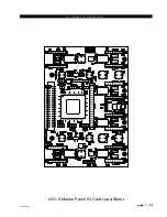
Page 63: ...D 9 May 2005 page 7 2 ...

Page 64: ...D 9 May 2005 page 7 3 ...

Page 65: ...D 9 May 2005 page 7 4 ...

Page 66: ...D 9 May 2005 page 7 5 ...

Page 67: ...page 7 6 D 9 May 2005 ...

Page 68: ...D 9 May 2005 page 7 7 ...

Page 69: ...page 7 8 IP 9 4 Inputs Panel Switch Card Load Sheet D 9 May 2005 ...

Page 70: ...page 7 9 D 9 Oct 2003 ...

Page 71: ...page 7 2 D 9 Oct 2003 S C H E M A T I C D R A W I N G S IQ 9 IQ Card Load Sheet page 7 10 ...

Page 72: ...page 7 11 D 9 Oct 2003 ...

Page 73: ...page 7 12 D 9 Oct 2003 ...

Page 74: ...page 7 13 D 9 Oct 2003 ...

Page 75: ...page 7 14 D 9 Oct 2003 ...

Page 76: ...page 7 15 D 9 Oct 2003 ...

Page 77: ...page 7 16 MN 9 Control Panel Switch Card Load Sheet D 9 Oct 2003 ...

Page 78: ...D 9 May 2005 page 7 17 ...

Page 79: ...D 9 May 2005 page 7 18 ...

Page 80: ...page 7 19 MFS 9 4 Master Panel Switch Card Load Sheet D 9 May 2005 ...

Page 81: ... O GCK2 I GCK0 I GCK3 I GCK1 I I O I O I O I O I O Vref0 I O Vref5 I O I O I O I O I O I O I O I O I O I O I O I O I O Vref0 I O Vref5 I O I O D5 I O I O Vref3 I O I O I O Vref3 _________ PROGRAM DONE TMS TDI TDO I O I O Vref2 I O I O I O Vref2 D1 I O D2 I O I O I O I O I O I O Vref2 D3 I O I O I O I O IRDY I O TRDY I O D4 I O I O Vref3 I O I O I O I O D6 I O CCLK TCK I O I O Vref6 I O I O I O M2 ...

Page 82: ... SHDN DIN CH0 CH1 CH2 CH3 COM MODE ADS7841 U2 10 15 14 9 5 12 6 7 1 16 2 8 4 3 11 13 BUSY DOUT VCC VCC GND VREF DCLK ___ CS _____ SHDN DIN CH0 CH1 CH2 CH3 COM MODE ADS7841 U8 4 2 6 AD291 GND G78 D6 1N4002 R42 10 R45 10 R43 10 R44 10 R46 10 C64 0 1uF Q6 LM317 2 3 1 OUT IN ADJ GND G56 D5 1N4002 R40 10 R41 10 R37 10 R38 10 R39 10 C65 0 1uF Q7 1 3 2 LM317 OUT IN ADJ GND G12 D3 1N4002 R30 10 R29 10 R31...

Page 83: ...page 7 3 D 9 Oct 2003 S C H E M A T I C D R A W I N G S IQO 9 Master Panel IQ Card Load Sheet page 7 22 D 9 May 2005 ...

Page 84: ...D 9 Oct 2003 page 7 23 ...

Page 85: ...D 9 Oct 2003 page 7 24 ...

Page 86: ...D 9 Oct 2003 page 7 25 ...

Page 87: ...page 7 26 DCM 9 DCM Panel Switch Card Load Sheet D 9 Oct 2003 ...

Page 88: ...5919 5 6V Z8 1SMB5919 5 6V Z5 1SMB5919 5 6V Z12 1SMB5919 5 6V Z11 1SMB5919 5 6V Z6 1SMB5919 5 6V Z4 GND 2 43K R214 1 00K R212 0 01uF C271 5 76K R213 TP8 TP7 MBRD835 D7 1500uF C277 330uF C266 0 22uF C284 LM2679 7 6 5 4 3 2 1 Q12 FB GND CB VIN OUT CL SS L13 L12 6 19K R211 47uF C276 47uF C285 10uF C265 10uF C260 3 3V 1SMB5915 3 9V Z13 1SMB5915 3 9V Z10 1SMB5915 3 9V Z14 POLYSW F5 1 0A POLYSW F6 1 0A ...

Page 89: ... RD RD VCCR VEER 11 12 13 14 15 16 17 18 VEER GND 47uF C1 GND L2 L6 4 99K R30 4 99K R40 4 99K R42 4 99K R44 0 1uF C41 0 1uF C25 0 1uF C40 0 1uF C39 0 1uF C38 C28 0 1uF 0 1uF C18 0 1uF C51 3 3V 47 R85 47 R83 3 3V 3 3V 3 3V 3 3V 47 R84 47 R86 TXD TXD RXD RXD GND GND FTRJ1323 OT1 LOS RATESELECT MOD_DEF 0 MOD_DEF 2 TDIS TFAULT VEET MOD_DEF 1 1 2 3 4 5 6 7 8 9 VEER VEER 10 20 19 VEET TD VCCT VEET TD RD...

Page 90: ...21 20 18 17 16 15 14 10 9 8 7 6 5 4 3 2 U10 I O I O I O VREF0 I O VREF5 I O I O I O I O I O I O I O I O I O D0 DIN I O D7 I O BUSY DOUT I O INIT I O ____ CS I O I O ___ WRITE I O I O ______ I O I O I O I O I O VREF1 I O VREF4 I O I O I O I O I O VREF1 I O VREF4 I O I O I O I O I O I O I O I O I O I O I O I O I O VREF1 I O VREF4 I O I O I O I O I O I O GCK2 I GCK0 I GCK3 I GCK1 I I O I O I O I O I ...

Page 91: ... I O I O VREF0 I O VREF5 I O I O D6 I O I O VREF3 I O I O I O VREF3 _________ PROGRAM DONE TMS TDI TDO I O I O VREF2 I O I O I O VREF2 D1 I O D2 I O I O I O I O I O I O VREF2 D3 I O I O I O I O IRDY I O TRDY I O D4 I O I O VREF3 I O I O I O I O D5 I O CCLK TCK I O I O VREF6 I O I O I O M2 M1 M0 I O I O I O I O VREF7 I O I O I O VREF7 I O I O I O I O I O I O I O VREF7 I O I O I O I O IRDY I O TRDY ...

Page 92: ... I O I O I O I O I O I O VREF0 I O VREF5 I O I O D6 I O I O VREF3 I O I O I O VREF3 _________ PROGRAM DONE TMS TDI TDO I O I O VREF2 I O I O I O VREF2 D1 I O D2 I O I O I O I O I O I O VREF2 D3 I O I O I O I O IRDY I O TRDY I O D4 I O I O VREF3 I O I O I O I O D5 I O CCLK TCK I O I O VREF6 I O I O I O M2 M1 M0 I O I O I O I O VREF7 I O I O I O VREF7 I O I O I O I O I O I O I O VREF7 I O I O I O I ...

Page 93: ...I O I O I O VREF0 I O VREF5 I O I O I O I O I O I O I O I O I O I O I O I O I O VREF0 I O VREF5 I O I O D6 I O I O VREF3 I O I O I O VREF3 _________ PROGRAM DONE TMS TDI TDO I O I O VREF2 I O I O I O VREF2 D1 I O D2 I O I O I O I O I O I O VREF2 D3 I O I O I O I O IRDY I O TRDY I O D4 I O I O VREF3 I O I O I O I O D5 I O CCLK TCK I O I O VREF6 I O I O I O M2 M1 M0 I O I O I O I O VREF7 I O I O I O...

Page 94: ...10 DQ11 DQ12 DQ13 DQ14 DQ15 DQMH CLK CKE ___ CS ___ WE ____ A0 A1 A2 A3 A4 A5 A6 CAS A7 A8 ____ A9 A10 A11 BA0 BA1 DQML RAS MT48LC4M16 2 4 5 7 8 10 11 13 15 16 17 18 19 20 21 22 23 24 25 26 29 30 31 32 33 34 35 37 38 39 42 44 45 47 48 50 51 53 U9 DQ0 DQ1 DQ2 DQ3 DQ4 DQ5 DQ6 DQ7 DQ8 DQ9 DQ10 DQ11 DQ12 DQ13 DQ14 DQ15 DQMH CLK CKE ___ CS ___ WE ____ A0 A1 A2 A3 A4 A5 A6 CAS A7 A8 ____ A9 A10 A11 BA0 ...

Page 95: ...page 7 34 HC 9 Host Controller Card Load Sheet D 9 Apr 2008 ...

Page 96: ...page 7 35 D 9 Oct 2003 ...

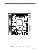
Page 97: ...page 7 36 BP 9 Back Plane Card Load Sheet D 9 Oct 2003 ...

Page 98: ...page 7 37 D 9 Oct 2003 ...

Page 99: ...page 7 4 D 9 Oct 2003 S C H E M A T I C D R A W I N G S BPR 9 Back Plane Repeater Card Load Sheet page 7 38 ...

Page 100: ...D 9 Oct 2003 page 7 39 ...

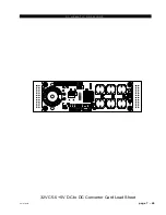
Page 101: ...page 7 5 D 9 Oct 2003 S C H E M A T I C D R A W I N G S 32VC5 5 5V DC to DC Converter Card Load Sheet page 7 40 ...

Page 102: ...D 9 Oct 2003 page 7 41 ...

Page 103: ...page 7 6 D 9 Oct 2003 S C H E M A T I C D R A W I N G S VU 9 VU Receiver Card Load Sheet page 7 42 ...

Page 104: ...page 7 43 D 9 Oct 2003 ...

Page 105: ...page 7 7 D 9 Oct 2003 S C H E M A T I C D R A W I N G S page 7 44 SW1 700 Switch Card Load Sheet ...

Page 106: ...page 7 45 D 9 Oct 2003 ...

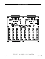
Page 107: ...page 7 8 D 9 Oct 2003 S C H E M A T I C D R A W I N G S PWI 5 1 Power Interface Card Load Sheet page 7 46 ...

Page 108: ... 3 Update Options A 3 Synchronize A 3 Battery Backup A 4 Appendix 2 Options Text File A 6 Introduction A 6 Modifying The Options Text File A 6 A Sample Example From The File A 7 A Second Example A 8 An Example File Complete A 9 Appendix 3 Replacement Parts List A 14 Spare Parts Kit A 17 Appendices ...

Page 109: ...page A 2 D 9 Jan 2007 A P P E N D I C E S Appendix 1 Contents Control Surface Clock A 3 Setting the Time A 3 Update Options A 3 Synchronize A 3 Battery Backup A 4 ...

Page 110: ...ce from the Main Menu which will display the following form 2 Enter an IP address of the control surface 3 SelectEdit Update Surface Clocksor press F5 key to update all surface clocks Update Options Select Edit Options from the Main Menu The Options form gives you different auto update options Select the appropriate option for your application Synchronize For the best accuracy synchronize the PC s...

Page 111: ...32 3V long life lithium battery it goes into the socket negative side in Note that the battery does NOT light up the clock display it powers the clock to keep it from losing count it will do this for 3 to 4 weeks To activate battery backup of the control surface s clock simply pull out the yellow strip from the HC 9 board as shown on the picture below ...

Page 112: ... 9 Jan 2007 A P P E N D I C E S Appendix 2 Contents Options Text File A 6 Introduction A 6 Modifying The Options Text File A 6 A Sample Example From The File A 7 A Second Example A 8 An Example File Complete A 9 ...

Page 113: ...re 2 When the FTP session connects you will see a list of files and folders that are on the surface One of those files is the Options Text file named as specified above Drag this file over to your PC s desktop so you can save a copy 3 Make any required changes to the copy of the file on your desktop according to the information in the following sections then save the file and drag its icon back to...

Page 114: ... 1 if the muting channel must be both ON and assigned to a main bus thus making it ON AIR before it will trigger the mute This specific example shows that the default setting is 0 for this option Please note that this may or may not be the case for your particular surface as the default option is subject to change The idea of how to use the file remains true The third line is not a comment this is...

Page 115: ...eset LED controlled by Surface SPARE1 2 SPARE2 2 SPARE3 2 SPARE4 2 SPARE5 2 SPARE6 2 SPARE7 2 SPARE8 2 SPARE9 2 SPARE10 2 SPARE11 2 SPARE12 2 Once again our first line is a comment line that shows the syntax used for this particular option In this case there are several code lines each one referring to a different spare or programmable button Thus the in the example syntax is replaced with a numbe...

Page 116: ... 3 Pre Fader Pre ON MM1 Ø MM2 Ø MM3 Ø MM4 Ø MM5 Ø MM6 Ø MM7 Ø MM8 Ø SPARE OPTIONS Syntax SPARE is the spare button number 1 12 is the mode default 2 Ø None Button presses are ignored LED controlled by DIO 1 Toggle Button state toggles on each press LED controlled by Surface 2 Momentary Button is active when held down LED controlled by Surface 3 Momentary Button is active when held down LED control...

Page 117: ...UT8 Ø DIRECT_OUT9 Ø DIRECT_OUT1Ø Ø DIRECT_OUT11 Ø DIRECT_OUT12 Ø DIRECT_OUT13 Ø DIRECT_OUT14 Ø DIRECT_OUT15 Ø DIRECT_OUT16 Ø DIRECT_OUT17 Ø DIRECT_OUT18 Ø DIRECT_OUT19 Ø DIRECT_OUT2Ø Ø DIRECT_OUT21 Ø DIRECT_OUT22 Ø DIRECT_OUT23 Ø DIRECT_OUT24 Ø DIRECT_OUT25 Ø DIRECT_OUT26 Ø DIRECT_OUT27 Ø DIRECT_OUT28 Ø DIRECT_OUT29 Ø DIRECT_OUT3Ø Ø DIRECT_OUT31 Ø DIRECT_OUT32 Ø DIRECT_OUT33 Ø DIRECT_OUT34 Ø DIREC...

Page 118: ...NE_VDIP 1 Syntax XYC_CHECKSUM 1 default use checksum in XYC messages Ø no checksum XYC_CHECKSUM 1 Syntax VU_RANGE Ø default 2Ø to 2Ødb 1 4Ø to 2Ødb VU_RANGE Ø Syntax MUTE_METHOD Ø default ON button 1 ON AIR MUTE_METHOD Ø Syntax PRESET_PLAY 1 new preset playback method Ø old preset core dump method PRESET_PLAY 1 Syntax HDW_LOGGER 1 use hardware logger Ø default no hardware logger HDW_LOGGER Ø Synta...

Page 119: ...fault 6Ø Hz NTSC 5Ø 5Ø Hz PAL FRAME_RATE 6Ø Syntax ACI_DISABLE_MSS Ø default send machine start stop DIOs whenever input channels go on off 1 supress machine start stop DIOs when input channels on off via ACI 2 supress machine start stop DIOs when input channels on off via remote on off DIO 3 supress machine start stop DIOs when input channels on off via ACI and or DIO ACI_DISABLE_MSS Ø ...

Page 120: ...se controls and components that inthecourseofnormalusemayneedmaintenance i e faders pots ON OFF switches etc A complete list of available components is shown on the next page Contact Wheatstone technical support for further information Wheatstone Corporation 600 Industrial Drive New Bern North Carolina USA 28562 may be reached by phone at 252 638 7000 fax 252 637 1285 electronic mail techsupport w...

Page 121: ...EMBLY FOR PANEL WITH MOTORIZED FADERS 005273 IQ 9 LOADED CARD IQ LOADED CARD ASSEMBLY FOR PANEL WITH STANDARD FADERS 005275 IQO 9 LOADED CARD IQ LOADED CARD ASSEMBLY FOR MASTER PANEL WITH STANDARD FADERS 005276 IQO 9M LOADED CARD IQ LOADED CARD ASSEMBLY FOR MASTER PANEL WITH MOTORIZED FADERS 005277 EI 5 1 LOADED CARD ENCODER LOADED CARD 005030 SW1 700 LOADED CARD LOADED SWITCH CARD 001977 HC 9 LOA...

Page 122: ...ED INSTALLED 510293 NKK SWITCH JB15 SWITCH W BRIGHTER GREEN LED AND SILICON GASKET 510289 NKK SWITCH JB15 SWITCH W BRIGHTER RED LED AND SILICON GASKET 510290 NKK SWITCH JB15 SWITCH W BRIGHTER YELLOW LED AND SILICON GASKET 510291 SWITCH CAP RED SWITCH CAP 530003 SWITCH CAP WHITE SWITCH CAP 530004 ENCODER 11MM ROTARY ENCODER 20MM SHAFT LENGTH ORDER W 005030 ENCODER KNOB 11MM BLACK PUSH ON KNOB 52010...

Page 123: ...1 LUMA BUTTON STYRENE WITH UV INHIBITOR BUTTON PRINTED B 530322 LUMA BUTTON STYRENE WITH UV INHIBITOR BUTTON PRINTED C 530323 LUMA BUTTON STYRENE WITH UV INHIBITOR BUTTON PRINTED D 530324 PLUG 5 PIN PLUG FOR 26 AWG 230030 PLUG 6 PIN PLUG FOR 26 AWG 230031 PLUG RIBBON 26 PIN RIBBON PLUG 250043 PLUG RIBBON 40 PIN RIBBON PLUG 250053 HEADER 40 PIN BOXED HEADER STRAIGHT 250056 HEADER 5 PIN JST HEADER 2...

Page 124: ...1 520003 FADER KNOB GREY FADER KNOB 1 520004 FADER KNOB ORANGE FADER KNOB 1 520005 FADER KNOB RED FADER KNOB 1 520006 FADER KNOB WHITE FADER KNOB 1 520007 FADER KNOB YELLOW FADER KNOB 1 520008 ENCODER KNOB 11MM BLACK PUSH ON KNOB 4 520105 ENCODER CAP PLAIN BLUE CAP FOR 11MM COLLET KNOB 1 530291 ENCODER CAP PLAIN GREEN CAP FOR 11MM COLLET KNOB 1 530292 ENCODER CAP PLAIN GREY CAP FOR 11MM COLLET KNO...

Reviews: