background image

600 Industrial Drive, New Bern, N.C. 28562 (tel 252-638-7000 / fax 252-637-1285)

T

echnical

 M

anual

EDGE

n

e T w o r k

 i

n T e r fa c e

Summary of Contents for EDGE

Page 1: ...600 Industrial Drive New Bern N C 28562 tel 252 638 7000 fax 252 637 1285 Technical Manual EDGE Network Interface ...

Page 2: ...Technical Manual Wheatstone Corporation January 2016 EDGE Network Interface ...

Page 3: ...600 Industrial Drive New Bern North Carolina 28562 tel 252 638 7000 fax 252 637 1285 Wheatstone EDGE Network Interface 2016 Wheatstone Corporation ...

Page 4: ...urce because it is generating a unique signal the mix and making it available to stream throughout the system Likewise PCs streaming audio from a file via the WheatNet IP driver can clearly be seen as a source 3 Destination A destination is the opposite of a source It is a signal that can accept any WheatNet IP stream A destination can take the received WheatNet IP stream and convert it to a physi...

Page 5: ...Settings 1 5 Routing Rules 1 6 Rack Mounting 1 7 Installation Tips 1 7 Energizing 1 7 EDGE Hardware Features 1 8 Network Switches 1 8 CAT6 Wiring 1 9 Software Tools 1 9 I O Connections 1 10 Audio Inputs 1 10 Analog XLR 1 10 Analog RJ 45 1 10 Digital RJ 45 1 10 Audio Outputs 1 11 Analog XLR 1 11 Analog RJ 45 1 11 Digital RJ 45 1 11 Logic Ports 1 11 Logic 1 6 RJ 45 1 11 Logic 7 12 RJ 45 1 12 Network...

Page 6: ...ing EDGE To The Devices Panel 3 3 System Info Pane 3 4 Device Properties 3 6 Blades Tab 3 6 Miscellaneous Tab 3 6 3rd Party Signal Name Prefix 3 6 PLL 3 7 Display Brightness 3 7 Receive Sequence Errors 3 7 Visibilities Tab 3 8 Delay Control Tab 3 9 Stream Meters Tab 3 9 Inpus and Outputs Tabs 3 10 EDGE GUI Menu 3 11 File 3 11 View 3 11 WheatNet IP System 3 11 Hardware 3 12 Help 3 13 Chapter 3 EDGE...

Page 7: ...Routing Rules 1 6 Rack Mounting 1 7 Installation Tips 1 7 Energizing 1 7 EDGE Hardware Features 1 8 Network Switches 1 8 CAT5e CAT6 Wiring 1 9 Software Tools 1 9 I O Connections 1 10 Audio Inputs 1 10 Analog XLR 1 10 Analog RJ 45 1 10 Digital RJ 45 1 10 Audio Outputs 1 11 Analog XLR 1 11 Analog RJ 45 1 11 Digital RJ 45 1 11 Logic Ports 1 11 Logic 1 6 RJ 45 1 11 Logic 7 12 RJ 45 1 12 Network Connec...

Page 8: ...cheme however creates a problem for the WheatNet IP system that is based on the use of high speed Ethernet switches for moving small Ethernet packets with minimal latency thru the network fabric The BLADEs ingest the small 25msec packets and only buffer a few of them before playing out the audio thereby limiting latency to less than 1 msec For real time production the latency for mix minus feeds i...

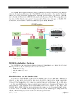
Page 9: ...AES 5ms Fixed 1 3 2 4 EDGE Function AUDIO DESTINATIONS AUDIO SOURCES BLADES BLADES EDGE Installation Options The EDGE may be installed at either the Studio or Transmitter sides of the IP STL link Where you decide to install it depends on a few factors IP Radio quality BLADE infrastructure Cost EDGE Installed on the Studio Side Fora Studio Edge IP STLapplication theEDGEconnectstotheWheatNet IPEther...

Page 10: ...t the Transmitter Side For a TX Edge IP STL application an IP radio is connected to the WheatNet IP Ethernet network on the Studio side and the EDGE is then located at the transmitter TX end The EDGE connects to another Ethernet switch along with the IP radio A BLADE co located at the transmitter site is not required but can provide valuable resources and functionality silence detection mixing aud...

Page 11: ...the audio in this return path will be 100 msec or more The BLADE buffers 5 msec packets upwards of 100 msec and then the DELAY setting of the EDGE would be in addition to that In the TX EDGE case return audio would simply be connected into the EDGE inputs Analog or AES and those sources would be available to any BLADE back in the Studio with the corresponding latency Note that these physical audio...

Page 12: ...in Navigator not all available routing path combinationsarevalid ThefollowingrulesapplywhenroutingEDGEsignalsinNavigator Route any surface mix or physical Blade input to any EDGE Destination Buffer Source signals may not be routed to other Buffer Destinations EDGE physical inputs may not be directly routed to any Buffer Destination WheatNet IPPCDriversignalsmaynotbedirectlyroutedtoanyBufferDestina...

Page 13: ...s inside If you have a problem the unit must be returned to Wheatstone Corporation for repair Installation Tips Place any surge protection circuits as close as possible to the EDGE or other device being protected Establish a low impedance common ground in your facility and try to route all grounds to that point Choose the best power conditioning UPS units that you can afford and suitable for your ...

Page 14: ...puts It also has four RJ 45 A1 IN A2 IN A1 OUT and A2 OUT connectors for analog input and output connections so you can choose your preferred connector type Four RJ 45 D3 IN D4 IN D3 OUT and D4 OUT connectors are for digital input and output connections Two RJ 45 connectors provide 12 logic ports which can be individually designated during set up as inputs or outputs Use these ports to wire the va...

Page 15: ...use Gigabit ports for the WheatNet IP to minimize link overload issues a smaller system will run just fine on an inexpensive unmanaged switch as long as it is a Gigabit switch It s all in the numbers It is important that the Ethernet network be properly set up in order for the EDGE to successfully join in with the rest of the WheatNet IP system CAT6 Wiring The next component of your WheatNet IP sy...

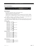
Page 16: ...f the EDGE will be sample rate converted to the system s chosen sample rate of 44 1kHz or 48kHz which is set via the WheatNet IP Navigator GUI Analog XLR XLR 1L Pin 1 SH XLR 1L Pin 2 HI Input 1 Lt XLR 1L Pin 3 LO XLR 1R Pin 1 SH XLR 1R Pin 2 HI Input 1 Rt XLR 1R Pin 3 LO XLR 2L Pin 1 SH XLR 2L Pin 2 HI Input 2 Lt XLR 2L Pin 3 LO XLR 2R Pin 1 SH XLR 2R Pin 2 HI Input 2 Rt XLR 2R Pin 3 LO Analog RJ ...

Page 17: ...t 2 Rt XLR 2R Pin 3 LO Analog RJ 45 RJ 45 A1 Pin 1 HI RJ 45 A1 Pin 2 LO RJ 45 A1 Pin 3 HI RJ 45 A1 Pin 6 LO RJ 45 A2 Pin 1 HI RJ 45 A2 Pin 2 LO RJ 45 A2 Pin 3 HI RJ 45 A2 Pin 6 LO Digital RJ 45 RJ 45 D3 Pin 1 HI RJ 45 D3 Pin 2 LO RJ 45 D4 Pin 1 HI RJ 45 D4 Pin 2 LO Logic Ports The EDGE has two LOGIC 1 6 and 7 12 RJ 45 connectors that provide 12 Universal logic ports LOGIC 1 6 RJ 45 RJ 45 Pin 1 Dig...

Page 18: ...nt and Auto MDIX allowing it to support straight through and crossover cables in any combination ThewiredEthernetinterfacecansupportuptofoursimultaneous connections to remote GUIs For typical CAT6 cable pinouts see below These connections are for communicating with the configuration computer via a network Ethernet RJ 45 Pin 1 TXD Pin 2 TXD Pin 3 RXD Pin 4 N C Pin 5 N C Pin 6 RXD Pin 7 N C Pin 8 N ...

Page 19: ...sover Cable 1 2 3 4 TXD TXD RXD RXD PIN 1 2 3 4 PIN RJ 45 Plug RJ 45 Plug White Orange 5 6 7 8 N C N C 5 6 7 8 Orange White Green Blue White Blue Green White Brown Brown White Green Green White Orange Blue White Blue Orange White Brown Brown N C N C RXD RXD TXD TXD N C N C N C N C ...

Page 20: ...N 1 OUTPUT 2 RT SH PIN 2 OUTPUT 2 RT HI PIN 3 OUTPUT 2 RT LO 1 2 3 4 5 6 7 8 INPUT 1 HI INPUT 1 LO A1 RJ 45 1 2 3 4 5 6 7 8 INPUT 3 AES HI INPUT 3 AES LO D3 RJ 45 1 2 3 4 5 6 7 8 INPUT 2 HI INPUT 2 LO A2 RJ 45 1 2 3 4 5 6 7 8 D4 RJ 45 INPUT 4 AES HI INPUT 4 AES LO ANALOG DIGITAL INPUTS 1 2 3 4 5 6 7 8 OUTPUT 1 HI OUTPUT 1 LO A1 RJ 45 1 2 3 4 5 6 7 8 OUTPUT 3 AES HI OUTPUT 3 AES LO D3 RJ 45 1 2 3 4...

Page 21: ...G E F R O N T P A N E L O P E R A T I O N EDGE Front Panel Operation Adding EDGE to the Peripheral Devices Tab 2 2 Front Panel Controls 2 3 OLED Display 2 3 EDGE Front Panel Configuration 2 4 Front Panel Menu Diagram 2 6 Chapter Contents ...

Page 22: ...theNavigatorGUIandmakesurethatSystem0isselectedintheSystempane Now to the right of the System pane select the Peripheral Devices tab Click the Add button on the far right to bring up the Add Peripheral Device dialog shown on right Type in a convenient Name and insert the IP Address of the EDGE being added Leave the TCP Port at the default setting of 60021 From the Host Blade drop down select the B...

Page 23: ...eed to do any con figuring or testing from the front panel The knob serves a dual purpose It is used to scroll through menu selections and pa rameter choices by rotating the knob and it is used to advance through parameter fields by pressing and releasing the knob The other control is the square BACK button You can t rotate this so we will only tell you to press it When we say this we also imply t...

Page 24: ...to the network If it is not con nected the RJ 45 icon will show red and there will be no dots In the center of the bottom line In or Out indicates whether the EDGE s signal meters are displaying input or output The WNIP on the right side of the bottom line will show green if the EDGE is connected to the Wheatnet IP system EDGE Front Panel Configuration Activating any of the front panel controls wi...

Page 25: ...s the gain levels for selected inputs and allows the user to set the gain level for each input Output Gain Displays the gain levels for selected outputs and allows the user to set the gain level for each output PLL Mode Selects mode as Local or Remote Meter Mode Sets the front panel meter mode for EDGE to show input or output signal levels Network Shows the current IP Address Net Mask and Gateway ...

Page 26: ...page 2 6 EDGE Network Jan 2016 E D G E F R O N T P A N E L O P E R A T I O N Front Panel Menu Diagram ...

Page 27: ... Info Pane 3 4 Device Properties 3 6 Blades Tab 3 6 Miscellaneous Tab 3 6 3rd Party Signal Name Prefix 3 6 PLL 3 7 Display Brightness 3 7 Receive Sequence Errors 3 7 Visibilities Tab 3 8 Delay Control Tab 3 9 Stream Meters Tab 3 9 Inpus and Outputs Tabs 3 10 EDGE GUI Menu 3 11 File 3 11 View 3 11 WheatNet IP System 3 11 Hardware 3 12 Help 3 13 ...

Page 28: ... a minimum number of mouse clicks The EDGE GUI screen is vertically divided into two parts with a Device Properties Pane on the left side and a System Info Pane on the right side Contents of the both Panes are change according to the tab selected You may access any tabs of these Panes by simply clicking on them At the bottom of the screen is a Devices Pane that displays a list of EDGE devices that...

Page 29: ...Name note that the system doesn t care what name you use it will display it for you so you can recognize the device but it will not otherwise make use of the name Click on the down arrow at the right end of the Device Type field and select Edge Then fill in the IP Address field with the IP address of the EDGE you are adding Your Add Device dialog should look something like this Click Ok The device...

Page 30: ... fill in and after a period of time will indicate the scan is done When the scan is complete you will see a screen like this the exact text is system dependent Click the Finish button You will be asked if you want to save the system information just gathered It is a good idea to save this information at some point in time Otherwise every time you starttheWheatnetEdgeSetupGUIyou llneed todoascantod...

Page 31: ...n example of what you might see on the Sources Destinations Salvos and Blades tabs It is important to note that Blade Picker function will use the last scan information you saved If you have changed configuration in regard to Blades present since last saving the scan information you should rescan and resave ...

Page 32: ...vicename Thedefault name is EDGE The EDGE uses the WheatNet IP 3rd Party interface to define signals for handling audio between the EDGE and the WheatNet IP system The names of these signals use the four character device name as the first four characters and then an appropriate description as the last characters Changingthedevicename allowscustomization of the signal names that can make it easier ...

Page 33: ...o a maximum of 16 The displays also have a screen saver mode After a specified time thedisplaybrightnesswillbeautomaticallydimmedtoanalternatebrightnesssetting When a button is pressed or an encoder is turned the brightness returns to the normal level Normal Level This control specifies the normal brightness level of the display The possible values vary from a low of 1 off to a high of 16 AutoDim ...

Page 34: ...st of channels in alphanu meric order when selecting sources on the EDGE Check Allow No Source if you want NoSource to be allowed for that channel If No Source is not allowed then the channel must always have a source selected Right clicking in the Channel area of the Visibilities tab pops up a menu with some useful shortcuts on it Copy Choose this item to copy the visibility set tings of the curr...

Page 35: ...r the delay until audio dropouts can be heard and then backing away from this setting The maximum delay of upwards of one second is provided for just confirming that the correct connections have been set up and it is then obvious with the large delay Notethatchangingthedelaysettingdoes not immediately change the buffering delay The buffer must first go empty in order to reset and then refill to ne...

Page 36: ... your mouse and the text box belowthesliderupdateswiththespecific gain value If you prefer you can drag your cursor over the number in the text box to highlight it and type in the gain value you want The gain adjustment is made in real time and will reflect instantly on the bargraph meters The system rounds off gain settings to the nearest 1 10th dB A balance control allows you to adjust the balan...

Page 37: ...t Edge Setup GUI or to change the GUI appearance Devices Usedtoshoworhidethe Devicessection System Info Used to show or hide the System Info section Stylized Used to toggle the Wheatnet Edge Setup GUI between a modern appearance and a more traditional one WheatNet IP System The WheatNet IP System menu is used to manage signal sets within the EDGE GUI File Open Used to open a saved signal set File ...

Page 38: ...WheatNet IP System System Scan from the GUI menu This will display the WheatNet IP System Scan screen System Scan was described in details earlier in the System Into Pane section on page 2 5 Hardware The Hardware menu is used to set up devices in respect to connecting to them and managing their configuration and software Add New Device Used to set up a new EDGE for the GUI to communicate with brin...

Page 39: ...ntly connected EDGE this information may be needed in the event that Wheatstone Technical Support needs to be contacted about your unit Update Used to change the software version of the currently connected EDGE Reboot Used to reboot the currently connected EDGE this is used primarily after doing a software update a confirm dialog allows you to change your mind Help The Help menu gives additional i...

Reviews: