page 3 – 7
EDGE Network / Jan 2016
E D G E G U I
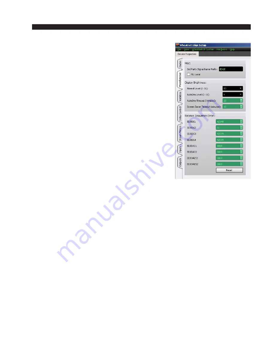
PLL
The EDGE and BLADEs both use ethernet packets for
sample rate clock synchronization. The IP radio inherently
adds a substantial jitter to these timing reference packets.
In order to overcome the jitter, the error integration interval
and overall loop locking must be extended significantly.
A PLL MODE selection is provided to accommodate for
this. In the Studio located EDGE case, the PLL MODE is
set for local since the jitter only is occurring at the far end
of the IP radio link. The BLADE at the far end will need
to be set to SLOW PLL mode for that unit only. In the
Transmitter located EDGE case, the EDGE PLL MODE is
set to REMOTE.
The check box allows you to switch between the PLL
modes:
•
When the check box is unchecked the PLL Local text
displays next to check box.
•
When the check box is checked the PLL Remote text
displays next to check box.
Display Brightness
The brightness of the displays can be controlled globally
by the settings in this region. The displays brightness varies from a setting of 1 (which is
off) to a maximum of 16. The displays also have a screen-saver mode. After a specified
time, the display brightness will be automatically dimmed to an alternate brightness setting.
When a button is pressed or an encoder is turned, the brightness returns to the normal level.
• Normal Level – This control specifies the normal brightness level of the display.
The possible values vary from a low of 1 (off) to a high of 16.
• AutoDim Level – This control specifies the brightness level to be used when the
displays are in screen‑saver mode. The possible values vary from a low of 1 (off)
to a high of 16.
• AutoDim Timeout – This control specifies how long (in minutes) to wait before
display is automatically dimmed. The allowed values range from 20 to 59 minutes.
• Screen Saver Timeout – This control specifies how long (in minutes) to wait before
entering screen‑saver mode. The allowed values range from 0 to 45 minutes.
Receive Sequence Errors
The EDGE is monitoring the RTP sequence number field of the stream and incrementing
counters for each stream when a sequence error is detected. When the IP radio is dropping
packets these counters will respectively increment. These counters may assist in qualifying
the IP radio settings and quality of RF link. Error rates of less than 10 increments per hour
are probably satisfactory.


