page 1 – 13
FM-531HD / May 2013
G E N E R A L I N F O R M A T I O N
Rear Panel Connections
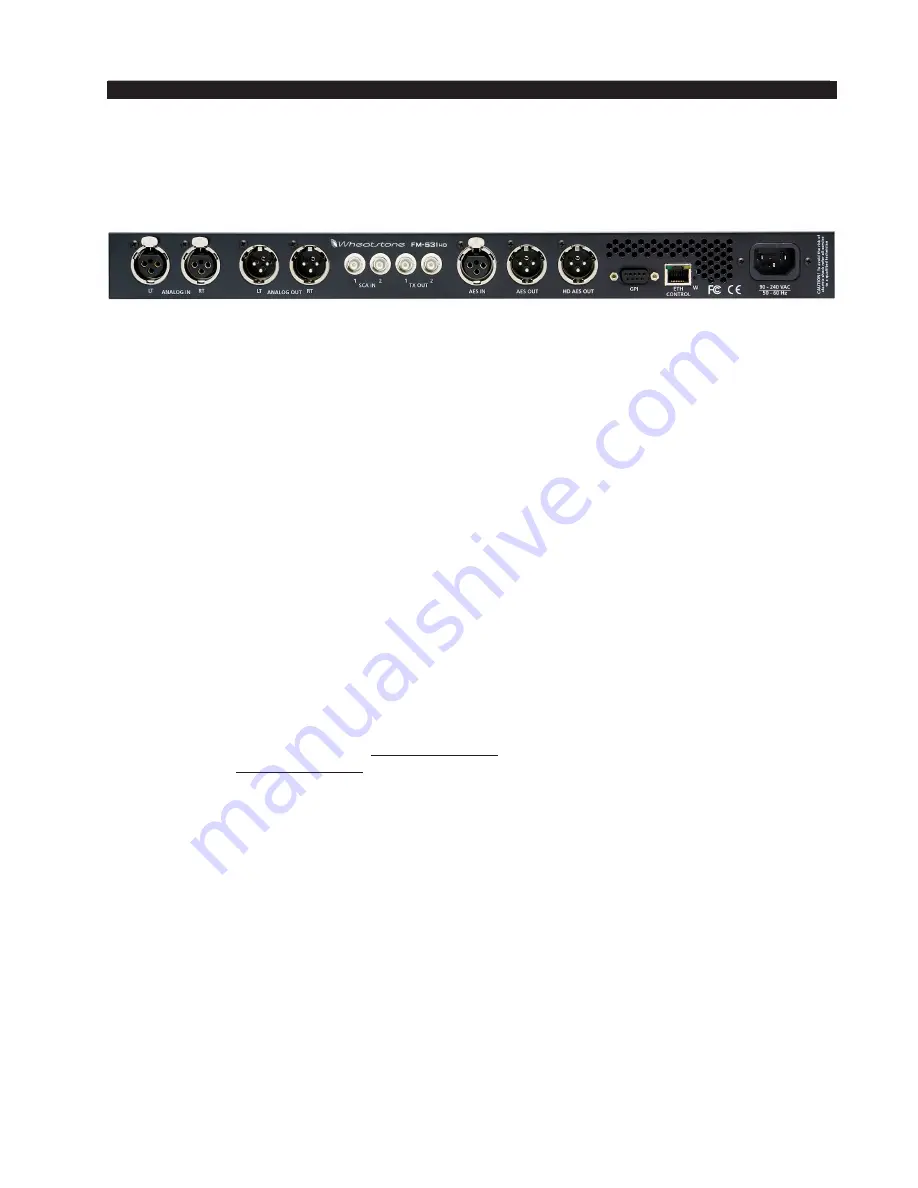
The image below shows the rear panel of the FM‑531HD and the location of vari‑
ous connectors associated with an installation:
All audio input and output, control, Ethernet, and power supply connections are
made via connectors on the processor’s rear panel.
The FM‑531HD’s rear panel connectors from left to right are:
Analog Left Channel In
Analog Right Channel In
Analog Left Channel Out*
Analog Right Channel Out*
SCA-1 Input
SCA-2 Input
TX-1 Out
TX-2 Out
AES Digital Input
AES Digital/baseband192 Out
HD AES Digital Out
GPI Input
Ethernet Control/WheatNet-IP Interface
IEC Standard male AC Power Input
*
When FM-531HD’s output mode is set to Composite Multiplex, the Analog left and right output XLR connec-
tors emit a balanced Composite Multiplex signal. A balanced signal is preferred when interfacing with exciters
having a floating and differential MPX input (most modern exciters do) and can provide a lower overall noise
floor than an unbalanced MPX circuit.
The listed connections are made via various connectors mounted on the FM‑531HD’s
rear panel.
• Seven XLR connectors are provided for analog and digital audio input and output
connections.
• Four BNC connectors are provided for SCA inputs and TX (transmitter) out, or
Composite Multiplex (MPX) connections.
• One RJ-45 connector is provided for Ethernet connection and WheatNet IP audio
streaming.
• One DB-9 connector provides 8 GPI inputs (for selecting presets in the first eight
storage slots). The pinout drawings in the Appendix summarize wiring connections
for these features.
Summary of Contents for FM-531 HD
Page 2: ...Technical Manual Wheatstone Corporation May 2013 FM HD Digital Audio Processor FM 531hd...
Page 122: ...page A 2 FM 531HD May 2013 A P P E N D I C E S Appendix A General Specifications A 3 Contents...
Page 128: ...page A 8 FM 531HD May 2013 A P P E N D I C E S Appendix B FM 531HD GPI Interface A 9 Contents...


