background image

page  6 – 3

IP-12 / Sep 2011

S C H E M A T I C   D R A W I N G S

IP-12 / Jun 2012

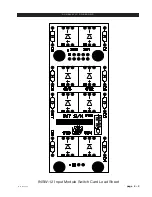
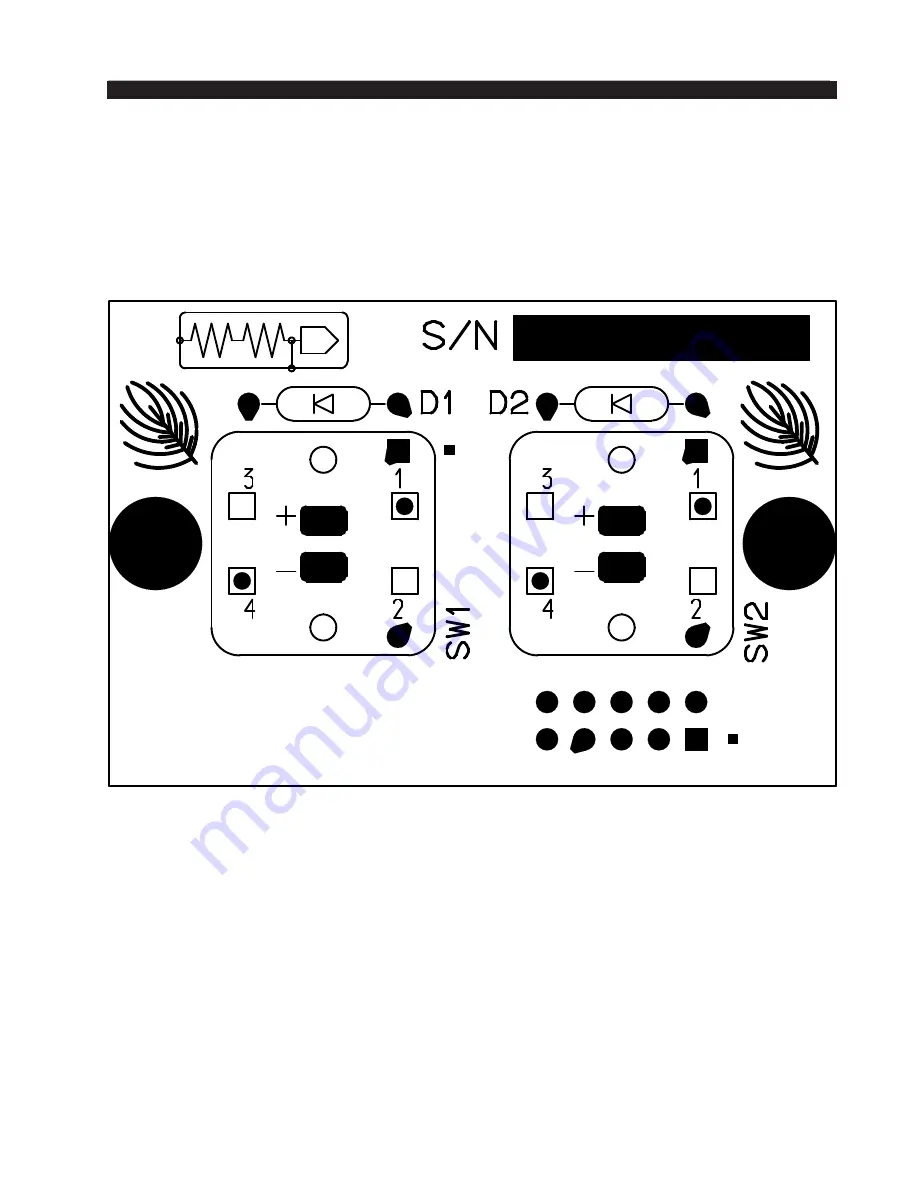
ONSW-12 Input Module On/Off Switch Card Load Sheet

page  6 – 5

Summary of Contents for IP-12

Page 1: ...IP 12 IP 16 Radio Control Surface TECHNICAL MANUAL 600 Industrial Drive New Bern North Carolina USA 28562...

Page 2: ...2 IP 16 Radio Control Surface Technical Manual 2014 Wheatstone Corporation WHEATSTONE CORPORATION 600 Industrial Drive New Bern North Carolina 28562 tel 252 638 7000 fax 252 637 1285 IP 12 IP 16 Dec 2...

Page 3: ...nd if not installed and used in accordance with the instructionmanual maycauseharmfulinterferencetoradiocommunications Opera tion of this equipment in a residential area is likely to cause harmful int...

Page 4: ...configuration of either the IP 12 IP 16 Control Surface or the Console BLADE However if you intend to install the IP 12 system as part of a larger WheatNet IP system you will need to change the defau...

Page 5: ...g like this Now to the right of the System pane select the System 3rd Party Devices tab Click the Add button to bring up the Add 3rd Party Device dialog Type in a convenient Name and insert the IP Add...

Page 6: ...1 5 Energizing 1 5 Getting Started 2 2 Tabbed Navigation 2 3 System Info Pane 2 4 Engine Tab 2 6 Talent Access Tab 2 7 VDips Tab 2 8 Monitor Config Tab 2 11 Buttons Tab 2 12 Visibilities Tab 2 13 GUI...

Page 7: ...ontrol 3 7 TB Talkback Button 3 7 HEADPHONE Level Control 3 8 TIMER Buttons 3 8 EVENT Buttons 3 8 General Information 4 2 Installation Tips 4 2 Energizing 4 3 I O Connections 4 4 Inputs 4 4 Outputs 4...

Page 8: ...ad Sheet 6 3 ONSW 12 Input Module On Off Switch Card Schematic 6 4 Load Sheet 6 5 CRSW 12 Control Room Module Switch Card Schematic 6 6 Load Sheet 6 7 SCSW 12 Studio Control Module Switch Card Schemat...

Page 9: ...P 16 Dec 2014 G E N E R A L I N F O R M A T I O N Chapter Contents General Information Introduction 1 2 Control Surface Placement 1 3 Power Supply 1 4 Failsafe Dual Redundant Supply 1 4 Connections 1...

Page 10: ...A B source selector whose sources can be set via a rotary encoder in the master section Each input module has access to four program busses and has cue and talkback switches A 100mm long throw fader a...

Page 11: ...securely to the countertop Locate the IP 12 IP 16 on the counter and remove the screws that hold the first and the last modules in place two per module Carefully remove these modules from the frame At...

Page 12: ...rol room audio gear This source should be a separate feed from those powering lighting air conditioning or any other non audio machinery Failsafe Dual Redundant Supply Wheatstone failsafe power supply...

Page 13: ...rance at the bottom of the rear panel for cable passage Energizing Assuming the IP 12 IP 16 control surface is properly placed and its power supply correctly connected to the console you may now energ...

Page 14: ...M A T I O N During the control surface booting up process the meterbridge 8 character LED displays will show the surface s software version In the event that you need to consult thefactoryabouttheIP 1...

Page 15: ...Contents Surface Configuration Getting Started 2 2 Tabbed Navigation 2 3 System Info Pane 2 4 Engine Tab 2 6 Talent Access Tab 2 7 VDips Tab 2 8 Monitor Config Tab 2 11 Buttons Tab 2 12 Visibilities T...

Page 16: ...ated either next to the control surface or at a remote location TheIP 12 IP 16controlsurfacecomeswiththeIPSeriesConsoleSetupTool Graphical UserInterface GUI program intendedtobestraightforwardinsetup...

Page 17: ...lick Add to add a device to the list Edit to change the name of an IP 12 IP 16 or give the GUI a different IP address to talk to it on or Remove to delete the device currently highlighted in the list...

Page 18: ...GUI menu This will display the WheatNet IP System Scan screen Start by specifying the Host Blade IP Address This can be the IP address of any physical BLADE inthesystem Next clickStartScan Whenthescan...

Page 19: ...e of what you might see on the Sources tab remember your signal names and other information will almost surely be different than the data shown here As we discuss the GUI there will be times when we n...

Page 20: ...and STOP signals are sent in response to a command to turn a channel ON or OFF Channel ON and OFF commands can come from two different sources Surface a channel can be turned ON or OFF by a surface ac...

Page 21: ...Program A B Buttons is not checked the operator will not be able to use the A and B INPUT buttons to change fader sources Bus Assignments Use of the ASSIGN buttons PGM AUD AUX and OL to de termine th...

Page 22: ...is first started the VDips tab Signals list contains only one item Default If you select Default you will be editing the VDip settings of all sources in the system except those you have specifically...

Page 23: ...ck and select Paste This copies the VDip settings from the first signal to the second one Please note that all VDip settings apply to the programmed signal regardless of which fader the signal appears...

Page 24: ...s instead Studio Mutes Input channels can be programmed to mute the various monitors when the channel is ON There are four Studio Mutes checkboxes one for each monitor section plus one for CUE The che...

Page 25: ...onitor as an example adjust the STUDIO level control on the SC 12 to the desired level then check the Level Locked box in the Studio section of the Monitor Config tab The monitor output will remain at...

Page 26: ...do so Toggle in this mode the button acts like a toggle with one press turning it on and the next press turning it off the button is illuminated by the surface when in the on state and is not illumina...

Page 27: ...er when selecting sources on the IP 12 IP 16 Check Allow No Source if you want NOSOURCE to be allowed for that channel If NOSOURCE is not allowed then the channel must always have a source selected Ri...

Page 28: ...ed to get a list of all signals currently available in the system see page 2 4 this set can then be saved using File Save and then later recalled using File Open even if the IP 12 IP 16 is not connect...

Page 29: ...xcept the Name it is best to highlight the complete default entry delete it then type in the complete new entry In the IP Address Subnet and Gateway fields use the period aka dot to move from one octe...

Page 30: ...Switch 3 3 Control Room Module CR 12 3 4 CUE Level Control 3 4 SOFT KEY Buttons 3 4 ENCODER And TAKE Controls 3 5 Source Select Switches 3 5 Programming External Source Switches 3 5 CONTROL ROOM Level...

Page 31: ...ing after a short timeout and the source will not be changed A similar process is used to program a source for a button Press and hold the desired button until it flashes then rotate the ENCODER on th...

Page 32: ...ize the OL bus instead This allows the Bus Minus output to have different content when the channel is off than it does when the channel is on Both the base Bus Minus mix and the use of the OL bus as b...

Page 33: ...h the Control Room speakers there is the potential for feedback The amplified signal from the Control Room speakers is picked up by the microphone and amplified to a new higher level which then is onc...

Page 34: ...l source displays While in this state turning the ENCODER knob will cycle through the following items depending on the IP 12 IP 16 s software version this list may change IP 12 IP 16 IP Address IP 12...

Page 35: ...urface s meterbridge and a group of METERS select buttons located on the CR 12 module VU Meter Pairs VU meter pairs PROGRAM AUDITION and SWITCHED are stereo LED bargraph type meters The level of the s...

Page 36: ...l source signal The button will be lit when the monitor is assigned to its respective bus Programming External Source Switches External switches X1 and X2 may be programmed to select any allowed sourc...

Page 37: ...s of desired duration RESET has a dual mode capability if you depress it while the timer is counting the display will instantly reset to zero and start a fresh count if the timer is already stopped de...

Page 38: ...eral Information 4 2 Installation Tips 4 2 Energizing 4 3 I O Connections 4 4 Inputs 4 4 Outputs 4 6 Logic Ports 4 7 Console BLADE 88cb Input Output Pinout Drawing 4 8 Stand Alone System Setup 4 9 Net...

Page 39: ...that point Choose the best power conditioning UPS units that you can afford and suitable for your equipment focus on the features and options you need The better UPS products can prevent thousands of...

Page 40: ...ying two channels of digital audio Generic audio cable such as Belden 8451 may be used for interconnecting AES3 digital audio devices but only for distances of less than about 25 feet The actual cable...

Page 41: ...which can be individually designated during setup as inputs or outputs These ports are where you wire the various external switches indicators and control functions you need in your facility There are...

Page 42: ...tal input 8 should be the same either 44 1kHz or 48kHz as the system s chosen sample rate AES sources are by design stereo if the BLADE is not set to be stereo the appropriate Left or Right signal wit...

Page 43: ...J 45 Pin 4 HI RJ 45 Pin 5 LO RJ 45 Pin 7 HI RJ 45 Pin 8 LO STUDIO OUT XLR XLR 1 Pin 1 SH XLR 1 Pin 2 HI Studio Lt Out XLR 1 Pin 3 LO XLR 2 Pin 1 SH XLR 2 Pin 2 HI Studio Rt Out XLR 2 Pin 3 LO CR OUT X...

Page 44: ...45 connectors that provide 12 Universal logic ports LOGIC I O 1 6 RJ 45 RJ 45 Pin 1 Digital Ground RJ 45 Pin 2 Logic 1 In Out RJ 45 Pin 3 Logic 2 In Out RJ 45 Pin 4 Logic 3 In Out RJ 45 Pin 5 Logic 4...

Page 45: ...7 IN LO AES 8 IN HI AES 8 IN LO 1 2 3 4 5 6 7 8 RJ 45 MIC 1 OUT HI MIC 1 OUT LO MIC 2 OUT HI MIC 2 OUT LO MICS OUT 1 2 3 4 5 6 7 8 HDPN LT OUT HI HDPN LT OUT LO HDPN RT OUT HI HDPN RT OUT LO CUE LT OU...

Page 46: ...starts by showing System Wizard start up message on its front panel and then displays BLADE ID DISABLED Simply scroll the front panel knob one click for the display to change to BLADE ID 1 and press t...

Page 47: ...ront panel controls to make crosspoint connections First turn the encoder knob through the menu selections until OUTPUTS is shown Press the switch and the display will show the first audio destination...

Page 48: ...sed to choose a source for the headphone destination just as it can for any other one You can use the front panel encoder to set the front panel meter mode for the BLADE There are 16 LED bargraph mete...

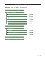
Page 49: ...014 W H E A T N E T I P 8 8 c b C O N S O L E B L A D E WheatNet IP 88cb Setup Wizard Tree scroll to change scroll to change scroll to change scroll to change scroll to change scroll to change scroll...

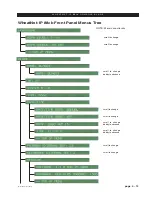
Page 50: ...L A D E scroll to change scroll to change scroll to change dobby to advance NOTE Menus are circular scroll to change scroll to change dobby to advance scroll to change scroll to change dobby to advanc...

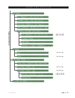
Page 51: ...P 16 Dec 2014 W H E A T N E T I P 8 8 c b C O N S O L E B L A D E scroll to change dobby to advance BLADE CONTINUED scroll to change dobby to advance scroll to change scroll to change scroll to change...

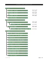
Page 52: ...E T I P 8 8 c b C O N S O L E B L A D E switch to select scroll to change switch to select scroll to change switch to select scroll to change switch to select scroll to change switch to select scroll...

Page 53: ...page 4 16 IP 12 IP 16 Dec 2014 W H E A T N E T I P 8 8 c b C O N S O L E B L A D E scroll to change dobby to advance scroll to change scroll to change...

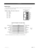
Page 54: ...16 Dec 2014 H A R D W A R E Host CPU HC 12 Chapter Contents Overview 5 2 Ethernet IP Addressing 5 2 Ethernet Interface Wiring 5 2 Hook Ups 5 3 CT20 RJ 45 Main Ethernet Connector 5 3 Typical Straight...

Page 55: ...provides details to the host application running on the HC 12 such as the specific audio hardware available Ethernet IP Addressing The Wheatstone IP 12 IP 16 control surface ships with the host contro...

Page 56: ...5 N C Pin 6 RXD Pin 7 N C Pin 8 N C Typical Straight Through Cable Used for connecting the host controller to your network hub Ethernet Connector RJ 45 1 2 3 4 5 6 7 8 TXD TXD RXD RXD N C N C N C N C...

Page 57: ...ings INSW 12 Input Module Switch Card Schematic 6 2 Load Sheet 6 3 ONSW 12 Input Module On Off Switch Card Schematic 6 4 Load Sheet 6 5 CRSW 12 Control Room Module Switch Card Schematic 6 6 Load Sheet...

Page 58: ...1 SW7 4 3 2 1 SW8 4 3 2 1 SW5 4 3 2 1 SW2 4 3 2 1 SW3 4 3 2 1 SW4 4 3 2 1 SW1 4148 D15 4148 D14 4148 D13 4148 D16 4148 D11 4148 D10 4148 D9 4148 D12 1N914 D5 1N914 D1 1N914 D6 1N914 D2 1N914 D7 1N914...

Page 59: ...page 6 2 IP 12 Sep 2011 S C H E M A T I C D R A W I N G S INSW 12 Input Module Switch Card Load Sheet page 6 3...

Page 60: ...SHEET SCALE REV SIZE DATE APPROVALS SA UR US Sergey Averin B A B A New Bern NC 28562 600 Industrial Drive 4148 D4 4148 D3 CT2 10 9 8 7 6 5 4 3 2 1 1 2 3 4 SW2 1N914 D1 SW1 4 3 2 1 1N914 D2 CT1 10 9 8...

Page 61: ...page 6 3 IP 12 Sep 2011 S C H E M A T I C D R A W I N G S IP 12 Jun 2012 ONSW 12 Input Module On Off Switch Card Load Sheet page 6 5...

Page 62: ...23 4148 D30 4148 D31 4148 D32 GND 2 1 3 CR1 10K CE1 2 4 5 1 3 ENCODER C E B A D 1N914 D16 1N914 D15 1N914 D14 1N914 D13 1N914 D1 1N914 D2 1N914 D3 1N914 D4 1N914 D5 1N914 D20 1N914 D19 1N914 D18 1N914...

Page 63: ...page 6 7 CRSW 12 Control Room Module Switch Card Load Sheet IP 12 Sep 2011...

Page 64: ...4 SW15 1 2 3 4 1 2 3 4 SW6 1 2 3 4 SW7 D12 1N914 D11 1N914 D10 1N914 D9 1N914 D13 1N914 1N914 D1 1N914 D2 1N914 D3 1N914 D4 1N914 D5 D8 1N914 D15 1N914 D14 1N914 1N914 D7 1N914 D6 1 2 3 4 5 6 7 8 9 1...

Page 65: ...page 6 9 SCSW 12 Studio Control Module Switch Card Load Sheet IP 12 Sep 2011...

Page 66: ...and components that in the course of normal use may need maintenance i e faders pots ON OFF switches etc Acomplete list of available components follows Contact Wheatstone technical support for further...

Page 67: ...DER KNOB BLACK FADER KNOB WITH WHITE LINE 520041 POT 10K SINGLE LINEAR PC VERTICAL MOUNT 9MM POT 500126 POT CONDUCTIVE PLASTIC SINGLE LINEAR 10K POT NO C D 1 8 SHAFT 500127 POT KNOB 15mm BLACK PUSH ON...

Page 68: ...ADER 5 PIN 098 HEADER 250064 HEADER 16 PIN BOXED HEADER STRAIGHT 250075 HEADER 10 PIN BOXED HEADER STRAIGHT 250077 HEADPHONE JACK RTS JACK 260005 CONNECTOR RJ45 SINGLE UPRIGHT SHIELDED CONNECTOR 26004...

Reviews: