Summary of Contents for B-111

Page 1: ...B c D Service Manual PRICE 5 00 nWHEEL HORSE 1I l1awn garden tractors PART NO 810063Rl PRINTED IN U S A ona w w w M y W h e e l H o r s e c o m ...

Page 2: ...g this publication Always observe common shop safety rules while performing service work Replace all parts that are worn or no longer serviceable Always replace expendable parts such as O rings gaskets and seals Section 1 lists specifications torque values and special instructions not listed in the general text It is advised that you become familiar with this information before making adjustments ...

Page 3: ... SECTION 2 PRE DELIVERY SERVICE SECTION 3 GENERAL MAINTENANCE SECTION 4 ENGINE SECTION 5 CLUTCH BRAKES TRANSMISSION TRANSAXLE SECTION 6 ELECTRICAL SYSTEM SECTION 7 ATTACHMENT LIFTS SECTION 8 CHASSIS SECTION 9 POWER TAKE OFF PTO _ _ w w w M y W h e e l H o r s e c o m ...

Page 4: ...s C Series 8 Speed Models Type Mechanical Mechanical All Gear All Gear Number of Forward Speeds 3 6 Number of Reverse Speeds 1 2 Approximate Ground Speeds at full throttle Gear Speed Gear low Range High Range 1st 1 7 mph 2 7 kph lst 5 mph 8 kph 2 mph 3 2 kph 2nd 3 6 mph 5 8 kph 2nd 8 mph 1 3 kph 3 2 mph 5 2 kph 3rd 5 5 mph 8 8 kph 3rd 1 4 mph 2 2 kph 5 5 mph 8 8 kph Rev 2 5 mph 4 kph Rev 6 mph 1 k...

Page 5: ...1 in 69 in 36 in 45 5 in 75 75 in 5901bs Automatic 104 em 175 3 em 92 em 116 em 192 em 266 kg 0 160 45 5 in 75 5 in 45 in 50 in 90 in 8751bs 116 em 192 em 114 em 127 em 229 em 394 kg 0 200 45 5 in 75 5 in 45 in 50 in 90 in 10251bs 116 em 192 em 114 em 127 em 229 em 461 kg TUNE UP GENERAL MAINTENANCE SPECIFICATIONS ENGINE TRACTOR POINT TIMING IGNITION SPARK SPARK DIRECTION IDLE GOVERNED MODEL GAP M...

Page 6: ...8 C SAE 5W 20 or 5W 30 lOW 10W 30 Below OOF 18 C SAE 10W or 10W 30 Diluted 10 with kerosene API Service SC MM SO MS or USE oil Kohler Engine Above 300 F 1 C SAE 30 lOW 3D 10W 40 30 to OOF _1 to lSoC SAE 10 5W 30 10W 30 10W 40 Below OOF 18 C SAE 5W 20 or 5W 30 API Service SC MM SO MS or liSE oil Onan Engine Above 30 F 1 0 C SAE 30 Below 30 F 1 C SAE 5W 30 API Service liSE oil Preferred viscosity Us...

Page 7: ...ight Code 1976 or equivalent Use Isomount No 106434 color code white for all models except C 81 Use Isomount No 106441 no color code for C St models Fuel hose must remain clear of Sundstrand Transmission Secure hose to top of transaxle and bottom of hood stand 1 4 12 17 O Series Models Fasten rectifier wire to inside edge of frame with wire clip Align front wheels for 1 16 to 1 8 inch 0 6 to 3 2 m...

Page 8: ...103029 DRIVEN COUPLING 920008 WASHER 4 REQUIRED ENGINE MOUNTING FACE 102622 COUPLING 920082 LOCKWASHER 908023 BOLT 106645 MOUNTING PLATE Fig 1 3 0 200 Flex Coupling 1 5 SECTION 1 0 200 cable tie headlight wire and ignition wire to the governor vacuum hose 0 200 PTO adjust PTO clutch hook to 1 13 16 inch 4 6 em from engine face to hook centerline Ad just clutch turnbuckle for 16 to 18 lb 3 6 to 4 0...

Page 9: ...4 05 5 H P 08 8 H P 10 10 H P 11 11 H P PRODUCT CATEGORY 6 42 42 WIDTH 48 48 WIDTH 56 56 WIDTH 59 59 WIDTH 12 12 H P 14 14 H P PRODUCT CATEGORY 7 16 16 H P 08 8 FURROW WIDTH 20 20 H P 12 12 FURROW WIDTH 05 5 CU FT CAPACITY PRODUCT CATEGORY 5 10 10 CU FT CAPACITY 26 26 CUT WI DTH 18 18 CU FT CAPACITY 30 30 CUT WI DTH 31 31 WIDTH 32 32 CUT WIDTH 38 38 WIDTH 36 36 CUT WIDTH 40 40 WIDTH 42 42 CUT WI D...

Page 10: ...ay is 0 to 015 inch 4 mm In some cases it may be necessary to add or remove a shim washer to achieve correct end play 015 Thin Shim Washer 050 Thick Shim Washer 1 lI O Snap Ring CS foaHUbCap 13t S O D Washer Fig 2 1 B Series Front Wheel Installation 050 ThiCk Shim Washer 1 lI Snap Ring C UbCap 1 1t2 O D Washer Fig 2 2 C Series Front Wheel Installation 2 t050 ThiCk Shim Washer 3 h 16x BOlt C8 Hub C...

Page 11: ...form a Y and line up the hole in the wheel hub with the hole in the steering shaft Insert a 1 4 punch through the hole to hold the steering wheel in position Install the 1 4 x 2 spirol pin by driving it in with a hammer as the spirol pin is driven in it should push the punch out 2 2 D SERIES With the front wheels straight ahead place the steering wheel on the steering shaft so that the spokes form...

Page 12: ...ngs with lockwashers and bolts on C Series models The seat springs are secured to the bottom 2 3 SECTION 2 of seat pivot plate on D Series tractors Remove the hard ware and re attach seat springs to top side of seat pivott plate See Fig 2 8 Fig 2 8 D Series Seat Installation Check Wiring and Attaching Hardware I Visually inspect for any loose connections and tight en as required Check routing of w...

Page 13: ...the tractor under full throttle and allow it to thoroughly warm up Bring the tractor to a stop using the brake return to neutral pedal Release the pedal if the tractor creeps in either direction set the neutral adjustment as described in Section 5 NOTES Check Front Wheel Alignment D Series Only With the tractor s wheels straight ahead there should be a small amount 1 16 to 1 8 inch l 5 to 3 mm of ...

Page 14: ... 21 Replace Fuel Filter O Series 100 Hours One Year 2 Clean and Lubricate PTO Clutch 0 200 100 Hours One Year 2 1 Refer to text for initial service interval for new tractors 2 Whichever occurs irst These service intervals are considered MAXI MUM under normal operating conditions Increase fre quency under extremely dirty or dusty conditions 3 1 ENGINE OIL Oil Level Never overfill the engine crankca...

Page 15: ...rm a gelatin like substance which seriously impairs and can even stop the flow of oil Increase the fre quency of oil and oil filter changes if the tractor is operated under extremely dusty conditions Before changing the oil start the engine and allow it to warm up This will allow the oil to flow more freely Shut off the engine and remove the key After adding the prescribed amount of oil check the ...

Page 16: ...placement filters with equivalent specifications 3 3 SECTION To prevent any dirt or other contaminants from entering the engine always cover the carbu retor air horn when the air cleaner is removed B SERIES To service the air filter remove the two screws air lift off the complete air cleaner assembly Remove tit screen and spacers from the foam element and remo l the element from the body of the ai...

Page 17: ...he precleaner 1 W SH 2 SQI lEEZE DAY 3 CO WITH 011 Fig 3 11 0 160 Air Cleaner BATTERY CHECK A hydrometer is used to measure specific gravity of the battery The water level in the battery should be at normal height when a hydrometer reading is taken Hydrometer readings should never be taken immediately after water has been added The water should be thoroughly mixed with the electrolyte by charging ...

Page 18: ...n 1 8 mm 025 in 6 mm 035 in 9 mm Tighten spark plug s to 22 ft Ibs 30 Nm 3 5 SECTION Fig 3 16 Spark Plug Gap Adjustment Points and Condenser B SERIES The breaker points on Briggs Stratton engines ara located under the flywheel Refer to Briggs Strattor Service and Repair Instructions Briggs Stratton Parl1 Number 270962 for correct flywheel removal pro cedures Fig 3 17 B Series Breaker Points C SERI...

Page 19: ...oint surfaces 5 If point replacement is necessary replace the breaker points with a new set Adjust point gap to an initial setting of 023 inch 6 mm 3 6 6 Remove the air intake hose that connects to the blower housing This provides an access to viewing the timing mark Fig 3 20 0 160 Breaker Point Gap 7 Check the ignition timing by connecting a continuity light across the ignition breaker points Con...

Page 20: ...mounting capscrews and rotate the governor until the timing mark is centered exactly in the sight hole Retighten flange mounting screws after exact timing is achieved 3 7 SECTION Fig 3 23 Governor Flange Mounting Screws Carburetor Adjustment Carburetors are adjusted in the factory and should nott have to be reset If however one of the following con ditions is noted the carburetor should be readjus...

Page 21: ...tle Turn MAIN fuel in until engine slows down lean side then out until it slows down again from overrich setting note positions of screw at both settings then set it about halfway between the two The IDLE fuel setting can then be adjusted in the same manner for smoothest idle Rough idle is often due to the idle speed being set too low check this also IDLE VALVE NEEDLE VALVE Fig 3 24 B Series Carbu...

Page 22: ...ee Fig 3 30 3 9 Fig 3 30 C 161 Twin Carburetor Adjustment FINAL ADJUSTMENT 1 Place governor speed control lever in IDLE position Hold throttle lever against idle stop and set idle speed ad justing screw to obtain 1450 R P M Turn idle valve slowly clockwise lean mixture until engine misses or R P M slows Then turn idle valve turn counterclockwise 2 Hold throttle shaft in closed position and adJust ...

Page 23: ... butterfly in fully closed position See Fig 4 2 C S1 Only Throttle cable is located on right side of dash panel leading under engine into a retainer clamp End of throttle wire inserts into first hole above stop pin See Fig 4 3 Adjust throttle by loosening cable retainer clamp Set throttle handle to full OPERATE position Tighten retainer clamp with throttle in fully open posi tion and stop pin agai...

Page 24: ... and Throttle Linkage ENGINE REMOVE AND REPLACE For engine repair operations refer to engine manu facturer literature Briggs and Stratton or Kohler or Wheel Horse Onan Engine Repair Manual B SERIES 1 Remove negative battery cable 2 Disconnect choke and throttle cables fuel line and all four electric lines magneto ground green alternator lights yellow alternator charge red starter black 3 Separate ...

Page 25: ...41 3 Disconnect electric wires to coil starter orange wire to rectifier plug headlights and PTO clutch Mark wire colors for replacement 4 Remove grille 5 Remove upper muffler clamps and four 4 bolts on grille shroud 6 Remove mufflers and complete hood and grille shroud assembly 7 Remove four 4 bolts holding engine to frame and slide engine forward until the flex coupling slides off pump drive shaf...

Page 26: ...le 2 Disconnect choke and throttle cables fuel lines hood stop cable and all electric lines battery cable to solenoid black magneto ground red yellow alternator plug 3 Remove the belt guard 4 Remove the hairpin cotter from the PTO clutch rod 5 Remove the PTO shaft clevis pin and pivot yoke away from shaft 6 Remove the PTO brake 7 Disengage the transmission drive clutch on automatic models or depr6...

Page 27: ...ove remaining PTO clutch housing from crankshaft 7 Remove idler pulley belt guides When removing belt guides pulleys are free if nuts are not replaced 5 1 8 Cut old belt or remove by working belt through geall shift access hole 9 Feed half the new belt through gearshift access hole aft end and half around the gearshift lever through thl access hole forward end 10 Place forward end of belt over eng...

Page 28: ...t a Speed Models The 8 speed clutch rod adjustment is made to adjust clutch pedal position To reposition pedal adjust the position of the threaded trunnion on the clutch rod at the left rear of the vehicle See Fig 5 6 The adjustment is more easily made by disconnecting the clutch rod at the clutch pedal Belt Guide Adjustment a Speed Models Belt guide tangs are located on the belt guard top and bot...

Page 29: ...an support bracket to top of transmission Remove fuel line and conduit clamps close fuel valve and disconnect fuel line at tank Secure fuel line to steering wheel to prevent fuel line from draining 8 Remove two 2 bolts and nuts holding seat pan support bracket not the fuel tank forward bolts 9 Lift off fuel tank along with both brackets and set tank aside 10 Drive spirol pin from range selector le...

Page 30: ... the neutral adjustment then adjust the brake band Fig 5 12 C Series Automatic Motion Control Neutral Adjustment Detent Alignment Adjustment After neutral has been adjusted check to see if the motion control lever is centered in the detent notch of the detent spring The spring incorporates slotted bolt holes so it may be adjusted as required to line up the neutral notch with the control rod See Fi...

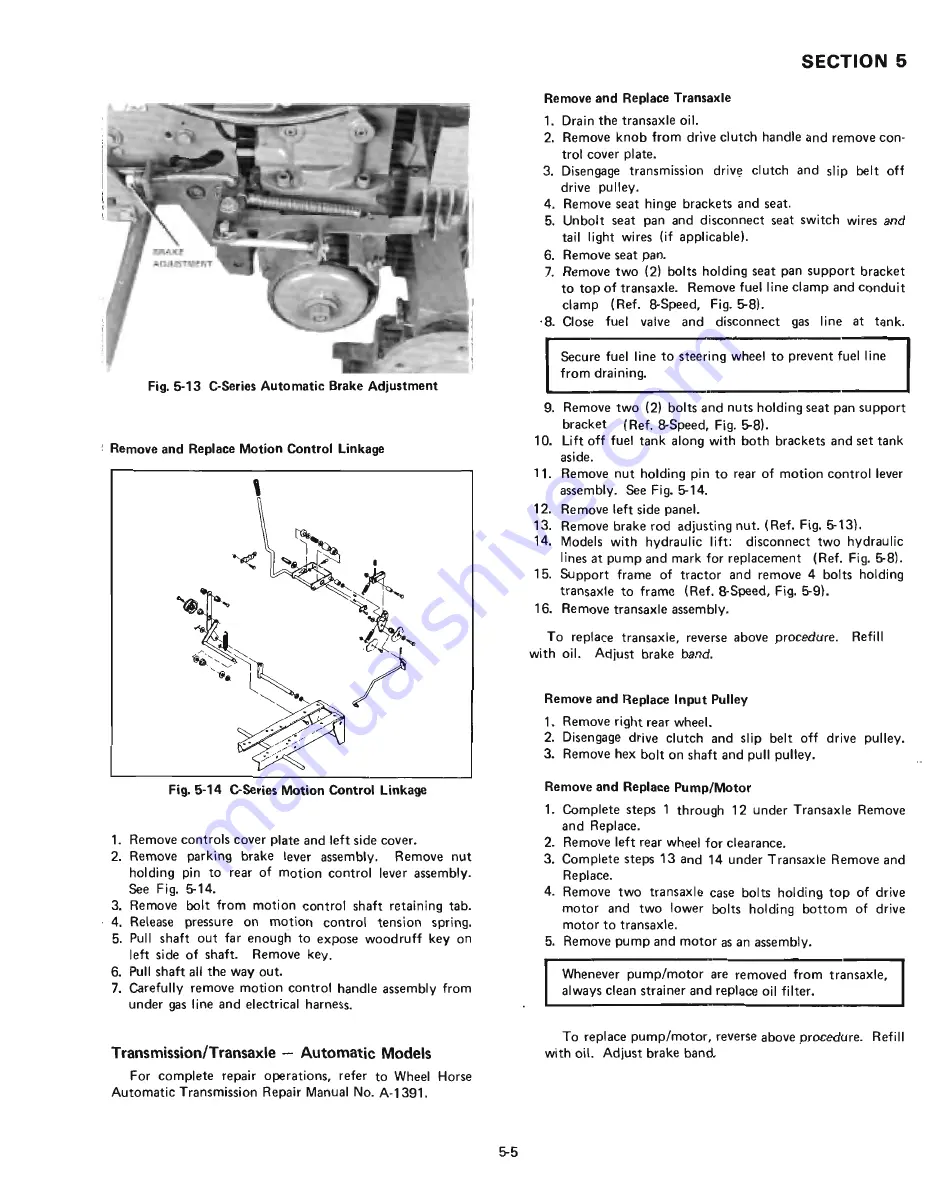
Page 31: ...el valve and disconnect gas line at tank Secure fuel line to steering wheel to prevent f Jel line from draining 9 Remove two 2 bolts and nuts holding seat pan support bracket Ref 8 Speed Fig 8 10 Lift off fuel tank along with both brackets and set tank aside 11 Remove nut holding pin to rear of motion control lever assembly See Fig 14 12 Remove left side panel 13 Remove brake rod adjusting nut Ref...

Page 32: ...f flats on the valve lands than does the reverse valve located at the front of the end cap housing The forward valve may be used in place of the reverse valve how ever under no circumstance should the reverse valve be substituted for the forward valve 5 J tr s 8ALl Fig 5 16 C Series Automatic Acceleration Valves 5 6 Implement Relief Charge Valve The implement relief valve is used to regulate hydra...

Page 33: ...ng temperature 4 Depress the brake pedal and release 5 Rotate the eccentric until the rear wheels stop This usually occurs at a point midway between forward and backward wheel rotation 6 Retighten the cap screw while holding the eccentric assembly from turning 7 Increase engine speed to full throttle 8 Move speed control lever in both directions and return it to neutral with the pedal Repeat sever...

Page 34: ... 4 Front brake adjustment is only required if the linkage is removed The jam nuts are adjusted so the spacer just contacts the spring and the spring remains free to turn See Fig 5 22 5 8 Parking Brake Adjustment Fig 5 24 D Series Park Brake Adjustment 1 Depress brake pedal and pull up on park brake knob locking it in the notch 2 Adjust nuts on rear rod to hold brake pedal fully de pressed 3 Depres...

Page 35: ...front butt plate to case bolts 11 Remove four top frame plate to transaxle bolts Fig 5 27 Transaxle Top Bolts 12 Lower the transaxle keeping it aligned between the butt plate and the frame angles to prevent binding 5 9 SECTION 5 Fig 5 28 Lowering Transaxle Fig 5 29 Transaxle Removed Transaxle Installation 1 Install new seal rings on the motor manifold mountingl pad The two large high pressure port...

Page 36: ...into place Prevent binding between the front plate and the angle brackets 5 10 Fig 5 32 Raising Transaxle 5 Start the top four case bolts using a punch for align ment Leave them slightly loose at this time Fig 5 33 Transaxle Top Bolts 6 Align the front case holes with the butt plate using a punch 7 Install the four front bolts and washers making sure the transaxle is squarely against both plates 8...

Page 37: ...s on the top An oil drain pan should be placed under this area since there will be some oil loss 6 Disconnect the hydraulic lift tubes located at the top of the pump 7 Disconnect the temperature sending unit wire 8 Remove the two 5 16 inch bolts and nuts that hold the rear pump bracket to the steering gear support 9 Remove the bolt that attaches the front pump bracket to the left side panel 10 Rem...

Page 38: ... 10 Secure the left panel to the front bracket with the bolt and nut 11 Connect the hydraulic tubes to the pump fittings 12 Connect the temperature indicator wire to the sending unit Fig 5 38 Temperature Sending Unit 13 Install the two rear manifold to pump cap screws from underneath Place the 3 8 inch elastic stop nuts on top but do not tighten at this ti me 14 Remove the two aligning studs and i...

Page 39: ...e the nuts from the two bolts securing the top section of the motor to the transaxle Ref Fig 5 44 7 Remove the two lower motor to case cap screws which I thread into the case Ref Fig 5 43 i 8 Remove the motor 5 13 SECTION 5 Motor Installation Fig 5 43 Motor Mounting Area Fig 5 43 shows the motor mounting area with the intake screen pulled out The two cap screw holes on each side of the screen and ...

Page 40: ...the 0 rings 3 Remove the two cap screws and two hex head bolts and nuts holding the manifold to the pump 5 14 4 Remove these 0 rings being careful to keep dirt away from the open oil ports 5 Remove the manifold by turning it past the steering gear bracket and pulling it out towards rear of tractor Cover all open oil ports in both motor and pu keep loose dirt from entering J Manifold Installation I...

Page 41: ... attachment to the pump pad Leave the protective cover on this pad while the rear of the manifold is being connected to the hydraulic motor Fig 5 50 Positioning Front of Manifold 5 15 SECTION 5 Fig 5 51 Rear Manifold Pad in Place 5 Carefully hold the manifold in place 6 Align the bolt holes in the rear manifold pad with the bolt holes in the motor and install all four bolts Make sure special seal ...

Page 42: ...es are used a forward valve and a reverse valve See Fig 5 54 Although the acceleration valves look similar they are not alike The forward valve located at the rear of the end cap housing incorporates wider relief flats on the valve lands than does the reverse valve located at the front of the end cap housing The forward valve may be used in place of the reverse valve however under no circumstances...

Page 43: ...uctions To flush foreign matter from lines use kerosene or equivalent solvent To flush hydraulic lift valve and manifold allow solvent to flow through it To flush pump and motor it is necessary to dis assemble and overhaul NOTES To flush implement cylinder blow all oil out by pushing cylinder rod in and out Flush with solvent C 161 TWIN Same as C Series _ _ _ _ _ 5 17 w w w M y W h e e l H o r s e...

Page 44: ...e near the starter If the engine must be operated with the battery dis connected from the charging system always dis connect the DC output lead at the fuse capsule to avoid possible charging system damage Fig 6 1 B Series DC Output Diode and AC Output Lead 6 1 The alternator charging system normally requires no ser vice other than periodically checking that all exposed wiring and electrical connec...

Page 45: ...NTERLOCK SWITCH CWTCH HE ADLIGHTS OPTIONAL ON 8 81 I r 4 J I I I I I I I I I I I I I I J 1 I I i I I 1 I I I I I I J BROWN LIGHT SWITCH OPTIONAL ON B 8 1 BLUE Fig_6 6 B Series Wiring Diagram C SERIES Ignition System INTERLOCK SWITCH PTO Battery and coil ignition is used in the C Series The ignition switch continuity test is performed as fol lows with the switch totally disconnected Position OFF RU...

Page 46: ... initial ammeter reading quickly dropping off to zero Interlock Switches The C Series safety interlock system incorporates two switches One switch is actuated by the clutch pedal on 8 speed models and by the brake return to neutral pedal on automatic models See Fig 6 7 and Fig 6 8 Fig 6 7 C Series Clutch Pedal Interlock Switch 6 3 SECTION 6 Fig 6 8 C Series Automatic Foot Pedal Interlock Switch Th...

Page 47: ... switch and pull the switch from the seat pan Lighting Circuit The light circuit on C Series tractors optional on some models is powered by the battery The lights operate when the ignition switch is in the Run position A 20 amp SFE fuse is part of the light circuit The fuse is contained in a fuse capsule connected between the ignition switch and the light switch behind the dash panel Wiring Harnes...

Page 48: ...s Wiring Diagram D SERIES Ignition System The D Series utilizes battery and coil ignition Refer to C Series for ignition switch testing procedure Charging System Same as C Series The rectifier regulator is located behind the engine below the battery on the inside of the left side panel 6 5 Charging System Test Same as C Series Ammeter Test Same as C Series Interlock Switches The D Series safety in...

Page 49: ... switch remove the large nut from the switch and release from the holding bracket and dis connect wi res 6 6 0 200 The PTO interlock switch is located on the mechani cal PTO handle bracket under the hood To replace the switch remove the battery and engage the PTO for access to the switch nut See Fig 6 15 The 0 200 foot pedal switch location and replacement is identical to the 0 160 Seat Switch A s...

Page 50: ...trical circuit diagram for connections when servicing or replacing the entire harness See Fig 6 21 and 6 22 Fig 6 18 D Series Control Console Wiring 0 200 Shown I A LTERNA TOR SECTION 6 Fig 6 19 O Series Headlight and PTO Wiring 0 160 Shown 200 ONLY 200 ONLY Fig 6 20 O Series Harness Routing 6 7 w w w M y W h e e l H o r s e c o m ...

Page 51: ...AL r I I L I I LIGHT SW TCH a w a 3 WIRE CONNECTOR TAIL LIGHTS r o J W I w o I w a w SAFETY SWITCH HYDRO r I I l HOUR METER OPTIONAL SENDER IGNITION START SWITCH Fig 6 21 0 160 Wiring Diagram 6 8 w w w M y W h e e l H o r s e c o m ...

Page 52: ...HEADLIGHTS RED YELLOW DASH LIGHT LIGHT SWITCH TAIL LIGHTS o lJJ _ J m o lJJ a POS r YELLOW I I SENDER III OPTIONAL Fig 6 22 0 200 Wiring Diagram 6 9 u J m w w w M y W h e e l H o r s e c o m ...

Page 53: ...are connected correctly before reconnect ing the ground cable negative or dam age to alternator system components will result Never run the engine if the battery is re moved or if the battery is not connected to the charging system Serious damage to charging system components may result 6 10 CHARGING SYSTEM TEST The overall charging system is tested by placing a DC voltmeter across the battery ter...

Page 54: ...TO ENGINE MAGNETO TO ENGINE ALTERNATOR Fig 6 23 TO ENGINE STARTER C 161 Twin Harness Routing 6 11 I I w w w M y W h e e l H o r s e c o m ...

Page 55: ...II I I L r__J I I I I I I I 1 I I I I I I 01 I I I I I I I I I I I L _____ 11 r 3 1 91 ijJl LIGHT SWITCH 1 r TAIL LIGHTS D C OUTPUT Fig 6 24 C 161 Twin Wiring Diagram 6 12 SEAT SWITCH w w w M y W h e e l H o r s e c o m ...

Page 56: ...r Lift Cable to Hole and Clevis Hitch D of Bellcrank No 19 Mid Lift Trunnion Adjustment Adjust trunnion No 20 nut No 23 and eyebolt No 22 so rubber bumpers on mower press firmly on bottom of footrests when lift is fully raised Rear Lift Trunnion and Chain Adjustment Rear Mount Attachments The chain adjustment has two positions operational and transport For operation the implement clevis is placed ...

Page 57: ...emove circlip No 1 at end of hydraulic cylinder 2 Withdraw piston No 2 and all seals 3 Replace 0 rings gaskets and seals with parts supplied in rebuild kit shown as No 3 in Fig 7 3 7 2 Fig 7 3 C Series Hydraulic Lift Components Remove Hydraulic Valve 1 Remove left side panel exposing cylinder and four hy draulic hose connections See Fig 7 2 Mark two rear hoses for identification during reassembly ...

Page 58: ...ee Fig 7 2 6 Tilt valve for access to push nut and pin 7 Replace handle and reassemble using new push nut 7 3 SECTION 7 Overhaul Hydraulic Valve 1 Remove valve and hoses from tractor see Remove Hydraulic Valve Q Fig 7 7 C Series Hydraulic Valve Overhaul 2 Remove spool cap and 1 8 inch allen bolt 3 Replace 0 ring and spring When reassembling valve make sure Allen head clears washer under spring J R...

Page 59: ...clevis pin from cylinder rod 3_ Remove four 4 bolts from bellcrank pivot bearings 4 Lower bellcrank assembly through bottom of frame Remove Hydraulic Cylinder 1 Remove access cover plate in front of seat 2 Disconnect hoses from front and rear of cylinder Note connections for reinstallation See Fig 7 9 7 4 Fig 7 9 D Series Hydraulic Hose Routing 3 Remove cotter pin and clevis pin from cylinder rod ...

Page 60: ... ground cable 2 Remove switch nut from Iight switch On D 160 also remove switch nut from PTO switch 3 Remove top and two outside screws from lower instru ment panel Swing panel out of the way 4 Remove nut and clevis pin from valve handle 5 Slide handle off S link 6 Replace handle using new push nut supplied with new handle NOTES Overhaul Hydraulic Valve Same procedure as C Series Remove Hydraulic ...

Page 61: ...gainst bushing and tighten set screw Lower Adjustment Gear mesh is adjusted as follows 1 Remove cotter pin from lower steering shaft Fig 8 2 Band G Series lower Steering Adjustment 2 Add or remove enough shims so that 0 to 015 inch 4 mm end play remains in shaft SECTION e UPPER STEERING SHAFT LOWER STEERING SHAFT Fig 8 3 B Series Steering UPPER STEERING SHAFT LOWER STEERING SHAFT 8 1 Fig 8 4 C Ser...

Page 62: ...kes and insert if necessary Remove Steering Gear 1 Remove steering wheel and foam dust cover 2 Disconnect the drag link from steering gear lever 3 Cut any wire ties holding electrical wiring to steering column 4 Remove through bolts holding gear housing to steering gear bracket See Fig 8 6 5 Remove steering gear assembly from the bottom Fig 8 6 Steering Gear Bracket Install Steering Gear Steering ...

Page 63: ...e the cotter pin and adjusting plug from the end of the steering gear housing 5 Remove the steering post worm and bearings from the housing 8 3 SECTION 8 Fig 8 9 Adjusting Plug The disassembled steering gear is shown in Fig 8 10 Fig 8 10 Steering Gear Disassembled OverhauI Steering Gear Assembly 1 Place the main housing firmly in a vise 2 Lubricate and place the upper and lower ball bearings and r...

Page 64: ...e lever and housing as shown 11 Tighten the inside nut unti I the lever is just against the gauge washer 8 4 Fig 8 13 Lever Gauge Adjustment 12 Tighten the lock nut against the inside nut and remove the 3 32 inch gauge washer 13 Turn the steering shaft from full left to full right 14 Use a screwdriver to tighten the lever stud until the high spot slight drag is just felt as you pass through the ce...

Page 65: ... 1 Separate PTO linkage under frame by removing clevis pin and hairpin cotter at PTO clutch turnbuckle 2 Remove PTO brake adjustment screw and bracket 3 Remove PTO clutch cone assembly 4 Remove crankshaft bolt and bearing race 9 1 Fig 9 2 B Series PTO Clutch Removal 5 Relieve drive belt tension by depressing clutch pedal and remove PTO clutch housing from drive shaft Reverse above procedure for in...

Page 66: ...g the brake flange 6 Push on the brake flange until it bottoms out and reo tighten the four locknuts Do not over tighten 7 Turn PTa switch to Off position and remove ignition key 8 Recheck the gap at all four positions with a feeler gauge The gap should be between 010 and 015 inches 3 and 4mm Fig 9 4 0 160 PTa Adjustment 9 2 PTO Clutch Adjustment 0 200 To adjust the PTa clutch 1 Remove the grille ...

Page 67: ...nance 0 200 After each 100 hours of operation or one year which ever comes first the PTO clutch on the 0 200 should be cleaned and relubricated This maintenance is covered as part of Clutch Disassembly and Reassembly following 9 3 SECTION 9 Fig 9 9 0 200 PTO Clutch Brake Clutch Removal 1 Disconnect the clutch rod trunnion from the clutch bars 2 Loosen the two brake bracket bolts allowing the brake...

Page 68: ...ring Fig 9 14 0 200 Retaining Ring Removal 3 Lift the pulley off the front clutch hub 4_ Remove the one plain washer and the four spring wash ers Note the position of each washer as it is removed E F GS Fig 9 15 0 200 Clutch Plate and Washp rs Clutch Reassembly 0 200 1 Clean the front cI utch hu b 2 Apply a thin coat of moly grease on the hub where the washers and bearings go 3 Install the spring ...

Page 69: ...Clutch Bar 6 Install the 3 8 bolt and nut to hold the clutch bars to gether 7 Before tightening the bolt install the clutch hook wash er and cotter pin 9 5 SECTION 9 8 Make sure of the alignment of the two bars and then tighten the bolt and nut 9 Place the spacer washer inside the front hub next to the internal snap ring This determines the position of the hub on the crankshaft 10 Line up the keyw...

Page 70: ... Same as C Series PTO Thrust Bearing The C 161 Twin is equipped with a thrust bearing between the engine and the drive pulley The bearing must be preloaded if the drive pulley is ever loosened or removed To preload the thrust bearing assemble the PTO as described and engage the PTO Tighten the set screws in the drive pulley and disengage PTO 9 6 w w w M y W h e e l H o r s e c o m ...

Reviews: