


P84408
Sheet 2 of 4
H
NOTE
: 1. Anechoic dBA is measured in anechoic chamber with fast meter response. 2. Reverberant dBA is rated per UL 464, Standard for Audible Signal
Appliances. 3. As per ULC requirement, the -3dB off-axis is 15
°
and the -6dB off-axis is 30
°
.
WARNING: CHECK THE MINIMUM AND MAXIMUM OUTPUT OF THE POWER SUPPLY AND STANDBY BATTERY AND SUBTRACT THE
VOLTAGE DROP FROM THE CIRCUIT WIRING RESISTANCE TO DETERMINE THE APPLIED VOLTAGE TO THE STROBES.
WARNING: MAKE SURE THAT THE CURRENT REQUIRED BY ALL APPLIANCES THAT ARE CONNECTED TO THE SYSTEM’S PRIMARY
AND SECONDARY POWER SOURCES, NAC CIRCUITS, SM, DSM SYNC MODULES OR WHEELOCK’S POWER SUPPLIES DO NOT EXCEED
THE POWER SOURCES’ RATED CAPACITY OR THE CURRENT RATINGS OF ANY FUSES ON THE CIRCUITS TO WHICH THESE APPLIANCES
ARE WIRED. OVERLOADING POWER SOURCES OR EXCEEDING FUSE RATINGS COULD RESULT IN LOSS OF POWER AND FAILURE TO
ALERT OCCUPANTS DURING AN EMERGENCY, WHICH COULD RESULT IN PROPERTY DAMAGE AND SERIOUS INJURY OR DEATH TO
YOU AND/OR OTHERS.
When calculating the total current: use Table 1 to determine the highest value of “Rated Average Current” for an individual horn (across the expected operating voltage
range of the device); then multiply this value by the total number of devices; be sure to add the current for any other devices powered by the same source and include
any required safety factors.
WARNING: MAKE SURE THAT ALL FUSES USED ON SIGNALING CIRCUITS ARE RATED TO HANDLE THE MAXIMUM INRUSH OR PEAK
CURRENT FROM ALL APPLIANCES ON THOSE CIRCUITS. FAILURE TO DO THIS MAY RESULT IN LOSS OF POWER TO THE SIGNALING
CIRCUIT AND THE FAILURE OF ALL APPLIANCES ON THAT CIRCUIT TO OPERATE, WHICH COULD RESULT IN PROPERTY DAMAGE AND
SERIOUS INJURY OR DEATH TO YOU AND/OR OTHERS.
WIRING INFORMATION:
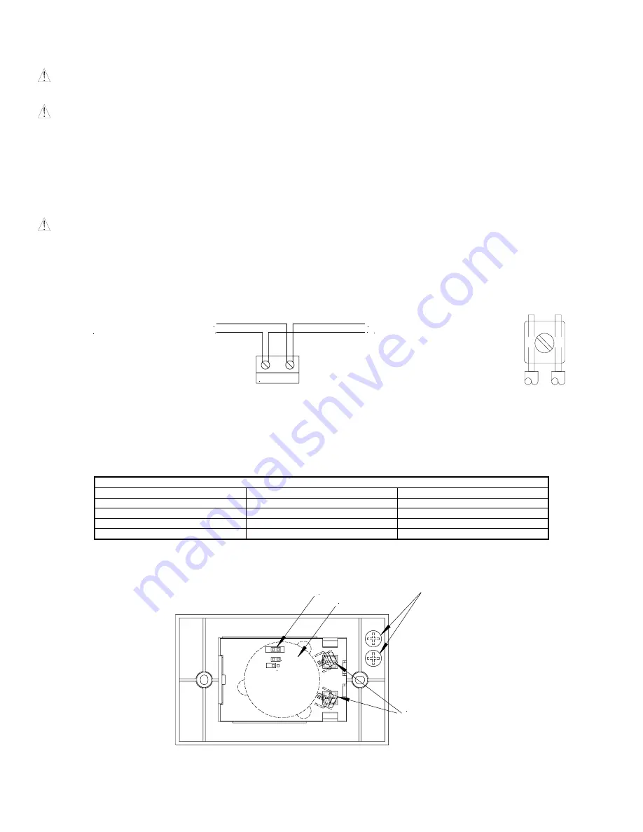
Figure 1:
Figure 2:
APPLIANCE
-
+
-
+
TO NEXT APPLIANCE
OR END OF LINE
RESISTOR (EOLR)
FROM PRECEDING
APPLIANCE OR FIRE ALARM
CONTROL PANEL (FACP)
1.
Appliances have in-out wiring terminals that accept two #12 to #18 American Wire Gauge (AWG) wires at each screw terminal. Strip leads 3/8 inches and
connect to screw terminals.
2.
Break all in-out wire runs on supervised circuits to assure integrity of circuit supervision shown in Figure 1. The polarity shown in the wiring diagrams is for the
operation of the appliances. The polarity is reversed by the FACP during supervision.
TEMPORAL (CODE 3) / NON-TEMPORAL (CONTINUOUS) JUMPER SETTINGS:
Table 2: Jumper Settings
FACP NAC
MIZ-24S
Result
Continuous Continuous Continuous
Continuous Temporal Code
3
Code 3
Continuous
Code 3
Continuous with SM/DSM *
Temporal
Synchronized Code 3
* Requires use of SM, DSM, or Wheelock’s Power Supplies in Wheelock Sync mode.
Figure 3: Temporal (Code 3) / Non-Temporal (Continuous) Select
PINS
LABEL
TERMINALS
NON-TEMPORAL
TEMPORAL
BEAUTY
PLUGS
NOTE
: Temporal (shorted) Non-Temporal (open)


