P84577 G
Sheet 12 of 14
7.0 TROUBLESHOOTING PROCEDURES:
The SP4-APS supervises all output zones and the module itself for trouble conditions. If a trouble condition is detected the
yellow GENERAL TROUBLE LED indicator is “
ON”
.
•
If the SP4-APS is connected to the SP40/2, the TROUBLE and the AUDIO SHORT LED indicators on the SP40/2 will
also be “
ON”
.
•
If the SP4-APS is connected to an Audio Booster (SPB-160, SPB-80/4, SPB-320), the TROUBLE and the AUDIO
SHORT LED indicators on the Audio Booster will also be “
ON”
.
OUT
IN
OUT
IN
OUT
IN
24 VDC
AUDIO
RS-485
ALARM
POWER
TROUBLE
Z1
Z2
Z3
Z4
EX1 EX2
IN
CLASS
B
A
SW
2
SP4-APS
JP1
NAC
CC
SW1
TB1
TB2
TB7
TB6
TB5
TB4
TB3
JP1
Shorted = 70Vrms
Open = 25Vrms
D3
7
D3
2
D3
6
D3
5
D4
1
D3
3
D4
2
D4
3
D3
8
D3
4
D3
9
D4
0
D44
D45
Zone 1
Short
Zone 1
Open
Zone 2
Short
Zone 2
Open
Zone 3
Short
Zone 3
Open
Zone 4
Short
Zone 4
Open
EX1
Short
EX1
Open
EX2
Short
EX2
Open
AUDIO TROUBLE LEDS
NETWORK
TROUBLE
LEDS
RS-485
IN-TRB
RS-485
OUT-TRB
GENERAL
TROUBLE
LED
POWER
LED
Figure 15:
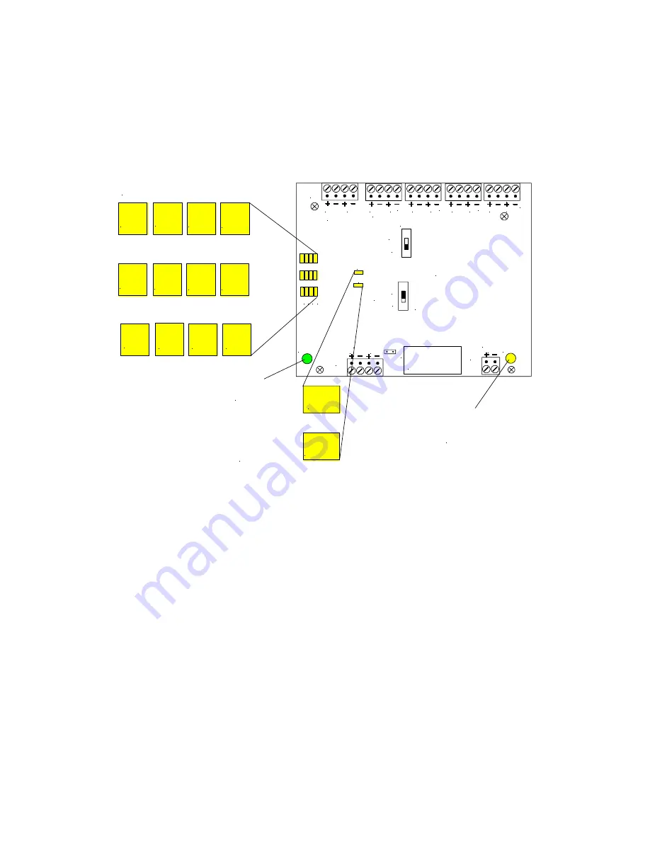
SP4-APS Power and Trouble LED Indicators
Figure 15 shows the Power and Trouble LED indicators on the SP4-APS PC board.
1.
Ensure that the green POWER LED is “ON”. If no LED's are lighted, check the 24VDC input power.
2.
Verify that SW1 (NAC/CC) switch is set to the desired position.
3.
Verify the SW2 (CLASS A or B) is set to the correct zone circuit configuration.
4.
Verify wiring is correct.
5.
If the yellow TROUBLE LED is “ON” an output circuit supervision trouble or module trouble is indicated. Remove the
SP4-APS cover and observe the 12 yellow AUDIO TROUBLE LED's as shown in Figure 14 to determine the reason
for the trouble using Table 3. (NETWORK TROUBLE LEDS are used when the SP4-APS is used with the Telephone
Zone Controller (SP4-TZC)).
6.
For each SHORT LED “ON”, check the speaker output wiring for that zone for a short or a faulty speaker appliance.
7.
For each OPEN LED “ON”, check the speaker wire run for that zone for an open or that the end of line resistor (if
applicable) is missing.


