background image

Page 4

ISP188 REPLACEMENT PARTS

LEFT SWEEP

7

6

5

4

3

2

1

8

RIGHT SWEEP

1

2

3

4

5

6

7

8

SPLIT-SWEEP

3

2

1

1

2

3

4

4

LEFT

RIGHT

Lamp 1

Lamp 2

Lamp 3

Lamp 4

Lamp 5

Lamp 6

Outlet

1

Outlet

5

Outlet

3

Outlet

7

Outlet

2

Outlet

6

Lamp 7

Lamp 8

Outlet

4

Outlet

8

TRAFFIC ADVISOR™

In order for the Traffic Advisor patterns to flash properly,

it is necessary for the lamps to be connected to the

ISP188 in the following pattern.

The Traffic Advisor (or T/A) mode is comprised of four,

traffic control-oriented flash patterns.

Traffic Advisor

Mode...

Control Wire #1 = LEFT SWEEP

Control Wire #2 = RIGHT SWEEP

Control Wire #3 = ALTERNATING FLASH

Control Wire #2 & #3 = SPLIT SWEEP

Dip Switches

Control Wires

The dip switch configuration for Traffic Advisor Mode:

Dip Switch 1 - ON

Dip Switch 2 - ON

Dip Switch 3 - ON

In this configuration, ap12VDC to the control

wires (using customer supplied switches) will have

the following results:

2

1

ALTERNATING FLASH

1

2

The T/A pattern mode is enabled as indicated in table 2.

5

4

WHEN MOUNTING UNIT

KEEP REAR SIDE CLEAR

OF OBSTRUCTIONS.

DIAG

NOS

TIX

WHE

LEN

5

8

AIR

FLOW

7 2

3

9

1

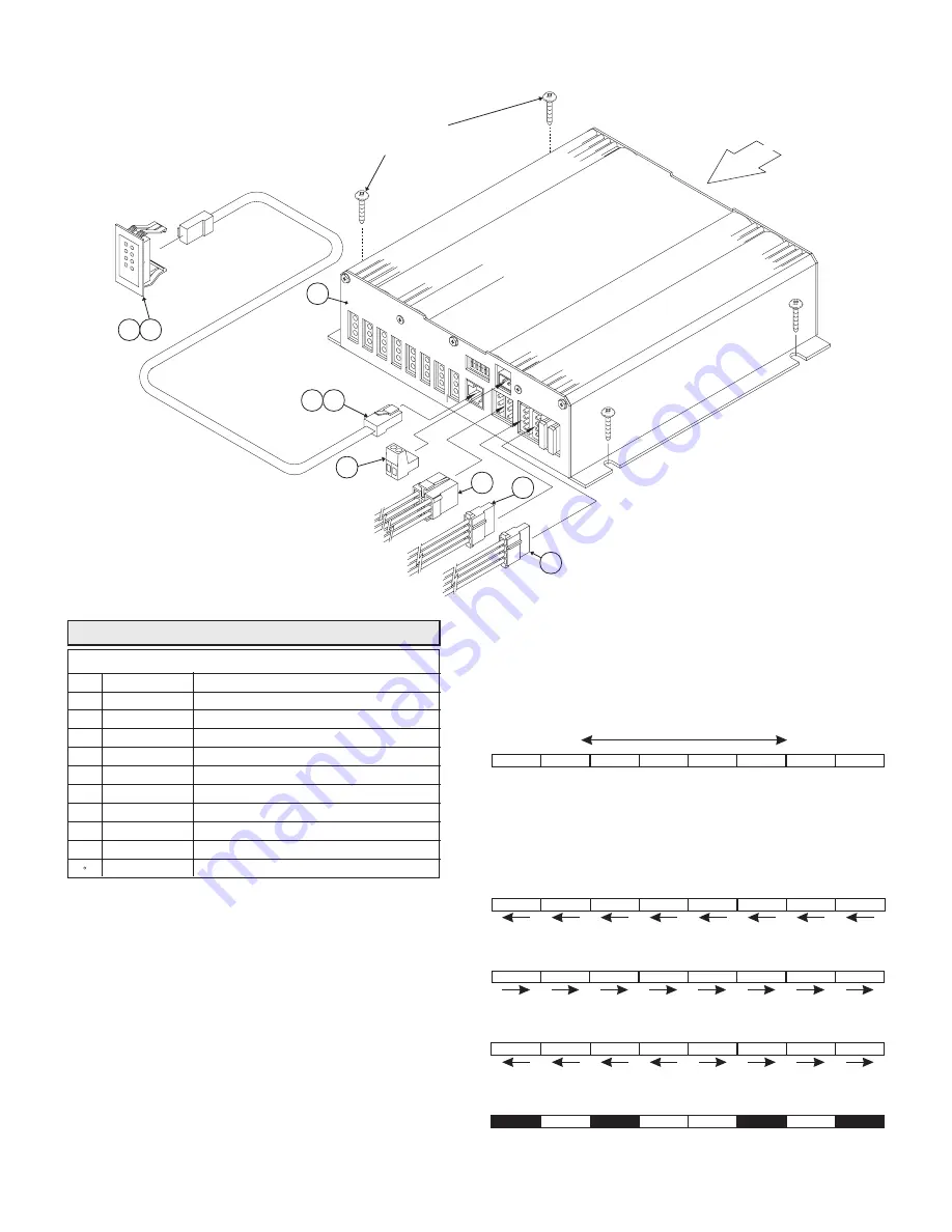
ISP188 PARTS LIST

01-0683125-00

ISP188 STROBE POWER SUPPLY

01-0662681-00

1

2

3

ISP188 FINAL ASSEMBLY

CONTROL CONNECTOR ASSEMBLY

46-0725613-00

4

46-0725945-00

PATTERN CONNECTOR ASSEMBLY

2 POS PHOENIX CONNECTOR

39CIJ02523-IJ

5

CABLE ASSY, 8 POS TELEPHONE 8’

02-0241485-08

6

01-0267643-00

7

02-0241485-25

CABLE ASSY, 8 POS TELEPHONE 25'

8

46-0725612-00

POWER CONNECTOR ASSEMBLY

9

DOT DIAGNOSTIC INDICATOR ASSEMBLY

25' TWISTED PAIR B-LINK CABLE

46-9641638250

REF

UPS DIAGNOSTIC INDICATOR ASSEMBLY

01-0267265-00

ITEM PART NUMBER

DESCRIPTION

N0.8 X 5/8 PAN HEAD

SHEET METAL SCREWS

(QUANTITY 4)

Summary of Contents for ISP188

Page 1: ...ets tape or Velcro clean the mounting surface with a 50 50 mix of isopropyl alcohol and water and dry thoroughly Do not install this product or route any wires in the deployment area of your air bag Equipment mounted or located in the air bag deployment area will damage or reduce the effectiveness of the air bag or become a projectile that could cause serious personal injury or death Refer to your...

Page 2: ...l Wire 3 2 4 6 8 Enabled SIM 2X2X4MN Mode Dip Switches The dip switch configuration for DOT188MN Mode Dip Switch 1 OFF Dip Switch 3 OFF Dip Switch 2 ON Dip Switch 8 OFF Control Wires Control Wire 1 Outlets 2 4 Enabled Control Wire 2 Outlets 6 8 Enabled Control Wire 3 Outlets 1 3 5 7 Enabled ALT 2X2X2X2 Mode Dip Switches The dip switch configuration for ALT 2X2X2X2 Mode Dip Switch 1 ON Dip Switch 3...

Page 3: ...rst III 2X TripleFlash PATTERN TYPE PATTERN WIRE Pattern Wire 1 BROWN Pattern Wire 2 WHITE Pattern Wire 3 GREY Pattern Wire 4 ORANGE V INPUT I IN 12 8V FLASHRATE JOULES HI JOULES LO OUTPUT POWER OUTPUT PER OUTLET 12 8VDC 20 22 5 WATTS TYP 180 WATTS 2 2 2 2 MIN 8 3 5 3 5 3 5 TYP 150 FPM MIN 18 AMPS TYP UNIT SPECIFICATIONS ISP188 WIRING DIAGRAM TO DESIRED LIGHTHEAD ASSEMBLY TYP 8 PLACES BLACK RED WH...

Page 4: ...Switch 1 ON Dip Switch 2 ON Dip Switch 3 ON In this configuration applying 12VDC to the control wires using customer supplied switches will have the following results 2 1 ALTERNATING FLASH 1 2 The T A pattern mode is enabled as indicated in table 2 5 4 WHEN MOUNTING UNIT KEEP REAR SIDE CLEAR OF OBSTRUCTIONS DIAGNOSTIX WHELEN 5 8 AIR FLOW 7 2 3 9 1 ISP188 PARTS LIST 01 0683125 00 ISP188 STROBE POWE...

Reviews: