background image

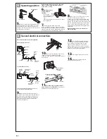
Operating position

C

5.

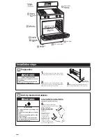
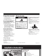
Remove cardboard shipping base from

under range. Open broiler drawer. Use a 3/8”
drive ratchet to lower rear leveling legs one-
half turn. Use channel lock pliers to lower front
leveling legs one-half turn. 

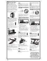
7.

If installing the range in a mobile 

home, you MUST secure the range to the floor.
Any method of securing the range is adequate as
long as it conforms to the “Manufactured Home
Construction and Safety Standard,” Page 2.

8.

Place rack in oven. Place level on rack,

first side to side; then front to back. 
If range is not level, pull range forward until
rear leveling leg is removed from the anti-tip
bracket. Use 3/8" drive ratchet and channel lock
pliers to adjust leveling legs up or down until
range is level. Push range back into position.
Check that rear leveling leg is engaged in anti-
tip bracket.

Note: Oven must be level for satisfactory
baking conditions.

Page 5

Before moving range across floor, check that
range is still on cardboard shipping base to
protect floor covering.

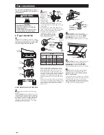
Gas and electrical connections

D

13.

Place burner grates over surface

burner.

14.

Plug power supply cord into 

grounded electrical outlet.

12.

Use a brush and liquid detergent 

to test all gas connections. Bubbles around
connections will indicate a leak. If a leak
appears, shut off gas valve controls and
tighten connections. Then check connections
again. Clean all detergent from range. Replace
storage drawer/close storage drawer.

rear leveling leg

front leveling leg

11.

Check that range regulator shutoff

valve is in the “on” position.

Open the manual

shutoff valve in the gas supply line.

manual shutoff valve

“open” position

gas supply

to range

6.

Making sure the

anti-tip bracket is
installed:

• Look for the 

anti-tip bracket
securely attached to 
floor.

• Slide range back so rear range foot is under 

anti-tip bracket. 

anti-tip
bracket

range foot

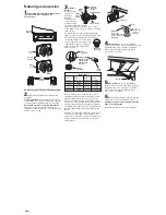
9.

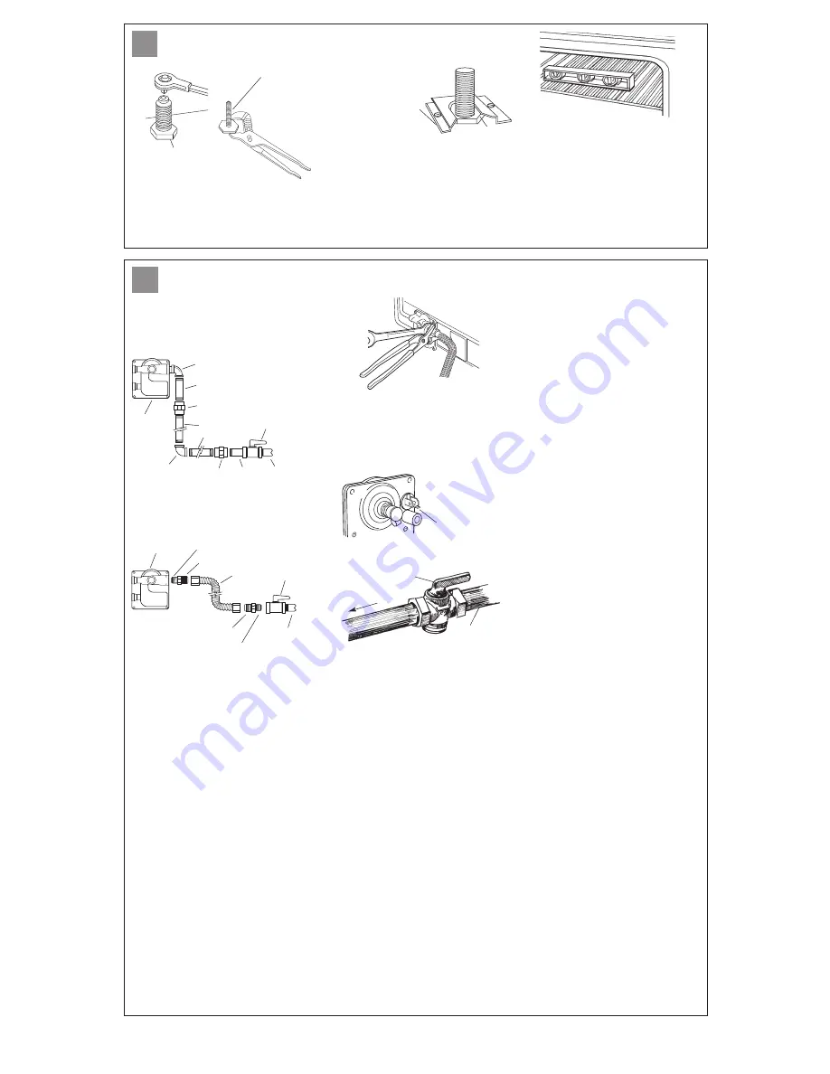
Apply pipe-joint compound made for

use with L. P. gas to the smaller thread ends of
the flexible connector adapters.  Attach one
adapter to the pressure regulator elbow and
the other adapter to the gas shutoff valve.
Tighten both adapters.

All connections must be wrench-tightened.

10.

Use 15/16" combination wrench and

channel lock pliers to attach the flexible
connector to the adapters.  Check that connector
is not kinked.

90˚elbow

1/2" to 3/4"
gas pipe

nipple

nipple

adapter

adapter

manual
gas
shutoff
valve

manual
gas
shutoff
valve

black iron
pipe

A 1/2" male pipe thread is needed for connection to
pressure regulator female pipe threads.

union

union

pressure
regulator

90˚elbow

1/2" to 3/4"
gas pipe

pressure
regulator

Typical rigid pipe connection

Typical flexible connection

flexible
connector

use pipe-joint
compound

use pipe-joint
compound

regulator shutoff

valve in “on”

position

Summary of Contents for 30" Freestanding Sealed Burner Gas Range with self-cleaning oven

Page 1: ...o call or call the dealer from whom you purchased this range The dealer is listed in the Yellow Pages of your phone directory under Appliances Household Major Service and Repair Call when you Have questions about range installation or operation Need to obtain the name and number of an authorized service company When you call you will need The range model number The range serial number Both numbers...

Page 2: ...Make sure you have everything necessary for correct installation It is the installer s responsibility to comply with installation clearances specified on the gas information label The gas information label and model serial rating plate are located on the frame behind the storage drawer Grounded electrical outlet is required See Electrical requirements Page 3 Proper gas supply connection must be av...

Page 3: ...sed The inlet pressure to the regulator should be as follows for proper operation NATURAL GAS Minimum pressure 5 inches WCP Maximum pressure 14 inches WCP L P GAS Minimum pressure 11 inches WCP Maximum pressure 14 inches WCP Contact local gas supplier if you are not sure about the inlet pressure Line pressure testing above 1 2 psi gauge 14 WCP The range and its individual manual shutoff valve must...

Page 4: ...allation steps Excessive Weight Hazard Use two or more people to move and install range Failure to follow this instruction can result in back or other injury WARNING Tip Over Hazard A child or adult can tip the range and be killed Connect anti tip bracket to rear range foot Reconnect the anti tip bracket if the range is moved Failure to follow these instructions can result in death or serious burn...

Page 5: ...k appears shut off gas valve controls and tighten connections Then check connections again Clean all detergent from range Replace storage drawer close storage drawer rear leveling leg front leveling leg 11 Check that range regulator shutoff valve is in the on position Open the manual shutoff valve in the gas supply line manual shutoff valve open position gas supply to range 6 Making sure the anti ...

Page 6: ...he air shutter until the proper flame appears Tighten screw You can check the burner flame by removing the flame spreader or by using a mirror Remove flame spreader Remove two screws from the front tabs of the flame spreader Lift front of the flame spreader and pull forward to remove tabs from rear of oven Using a mirror Insert mirror to one side of the burner Look into mirror to check flame stain...

Page 7: ...a time Place the Natural gas spuds on the spud card on the back of the range for future use Replace burners caps using both screws and burner grates Surface Propane Orifice Color burner Rate BTU hr Number Marking Left rear 8 000 L80 Green Lt Blue Left front 8 000 L80 Green Lt Blue Right front 8 000 L80 Green Lt Blue Right rear 5 000 L65 Green Brown L P Gas Nat gas pressure regulator orifice number...

Page 8: ... tape to the end of a 5 16 nut driver to fit snugly over the orifice spud Press driver down onto the spud of the left front burner and remove by turning spud counter clockwise and lifting it out Replace the L P gas spud with the appropriate Natural gas spud shown in the table Continue to replace the remaining orifice spuds one at a time Place the L P gas spuds on the spud card on the back of the r...

Page 9: ...er Both numbers are listed on the model serial rating plate located on the frame behind the broiler drawer Part No 8523780 2002 Whirlpool Corporation Printed in U S A Pages 2 2 2 3 Installation Instructions Moving the range CLOCK 8 8 88 TIMER TIMER When moving range slide range onto cardboard or hardboard to prevent damaging the floor covering If removing the range is necessary for cleaning or mai...

Reviews: