background image

INSTALLATION INSTRUCTIONS

30" (76 CM) FREESTANDING ELECTRIC RANGES

Table of Contents

RANGE SAFETY ............................................................................. 2

INSTALLATION REQUIREMENTS................................................ 3

Tools and Parts ............................................................................ 3
Location Requirements................................................................ 3
Electrical Requirements ............................................................... 5

INSTALLATION INSTRUCTIONS.................................................. 6

Unpack Range ............................................................................. 6
Install Anti-Tip Bracket................................................................. 6
Electrical Connection ................................................................... 8
Verify Anti-Tip Bracket Is Installed and Engaged...................... 11
Level Range ............................................................................... 11
Storage Drawer .......................................................................... 11
Oven Door .................................................................................. 11
Complete Installation ................................................................. 12
Moving the Range...................................................................... 12

IMPORTANT:


Save for local electrical inspector's use.

W10394782B

Summary of Contents for 4KWFC120MAW0

Page 1: ...cation Requirements 3 Electrical Requirements 5 INSTALLATION INSTRUCTIONS 6 Unpack Range 6 Install Anti Tip Bracket 6 Electrical Connection 8 Verify Anti Tip Bracket Is Installed and Engaged 11 Level Range 11 Storage Drawer 11 Oven Door 11 Complete Installation 12 Moving the Range 12 IMPORTANT Save for local electrical inspector s use W10394782B ...

Page 2: ... the safety alert symbol and either the word DANGER or WARNING These words mean follow instructions instructions DANGER WARNING Tip Over Hazard A child or adult can tip the range and be killed Install anti tip bracket to floor or wall per installation instructions Slide range back so rear range foot is engaged in the slot of the anti tip bracket Re engage anti tip bracket if range is moved Do not ...

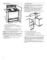
Page 3: ...ting plate is located on the frame behind a top corner of the door or either side of the drawer To eliminate the risk of burns or fire by reaching over heated surface units cabinet storage space located above the surface units should be avoided If cabinet storage is to be provided the risk can be reduced by installing a range hood that projects horizontally a minimum of 5 12 7 cm beyond the bottom...

Page 4: ...walls with zero clearance NOTE 24 61 0 cm minimum when bottom of wood or metal cabinet is covered by not less than 0 64 cm flame retardant millboard covered with not less than No 28 MSG sheet steel 0 015 0 4 mm stainless steel 0 024 0 6 mm aluminum or 0 020 0 5 mm copper 30 76 2 cm minimum clearance between the top of the cooking platform and the bottom of an uncovered wood or metal cabinet A 27 7...

Page 5: ...ircuit use a 50 amp rated cord with kit For 50 amp rated cord kits use kits that specify use with a nominal 1 34 9 mm diameter connection opening A circuit breaker is recommended The range can be connected directly to the circuit breaker box or fused disconnect through flexible or nonmetallic sheathed copper or aluminum cable See the Electrical Connection section Allow 2 to 3 ft 61 0 cm to 91 4 cm...

Page 6: ...ed on either the left side or right side of the cutout Position mounting bracket against the wall in the cutout so that the V notch of the bracket is 12 31 9 cm from centerline as shown 4 Drill two 3 mm holes that correspond to the bracket holes of the determined mounting method See the following illustrations A Shipping base A drive ratchet B Rear leveling leg C Wrench or pliers D Front leveling ...

Page 7: ...allow for final electrical connections Remove shipping base cardboard or hardboard from under range 7 Move range into its final location making sure rear leveling leg slides into anti tip bracket 8 Move range forward onto shipping base cardboard or hardboard to continue installing the range using the following installation instructions Rear position Front position Diagonal 2 options ...

Page 8: ...g Tighten strain relief screw against the power supply cord Power Supply Cord Direct Wire WARNING Electrical Shock Hazard Disconnect power before servicing Use a new 40 amp power supply cord Plug into a grounded outlet Failure to follow these instructions can result in death fire or electrical shock WARNING Electrical Shock Hazard Disconnect power before servicing Use 8 gauge copper or 6 gauge alu...

Page 9: ...re must be attached first 4 Use nut driver to connect the neutral red wire to the left terminal block post with one of the 10 32 hex nuts 5 Connect the line 1 black wire to the right terminal block post with one of the 10 32 hex nuts 6 Securely tighten hex nuts NOTE For power supply cord replacement use only a power cord rated at 250 volts minimum 40 amps or 50 amps that is marked for use with nom...

Page 10: ... 1 black wires Loosen do not remove the setscrew on the front of the terminal lug and insert exposed wire end through bottom of terminal lugs Securely tighten setscrew to torque as shown in the following Bare Wire Torque Specifications chart Bare Wire Torque Specifications Attaching terminal lugs to the terminal block 20 lbs in 2 3 N m 3 Use nut driver to connect the bare green ground wire to the ...

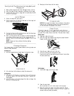
Page 11: ...ace the rear of the drawer inside the range so that the drawer stop notch is behind the drawer glide 2 Lower the drawer so that the edge of the slide rail drops into the slot in the drawer glide 3 Slowly push the drawer into the range NOTE When properly installed the rear slides on the bottom of the drawer will engage the base rails and the drawer will not tip when items are placed in the drawer O...

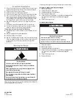
Page 12: ...ardboard or hardboard to avoid damaging the floor covering If removing the range is necessary for cleaning or maintenance For power supply cord connected ranges 1 Slide range forward 2 Unplug the power supply cord 3 Complete cleaning or maintenance 4 Plug in power supply cord 5 Check that the anti tip bracket is installed and engaged See the Verify Anti Tip Bracket Is Installed and Engaged section...

Reviews: