background image

Summary of Contents for 8205142

Page 1: ...es in Rear Wall 8 Attach Mounting Plate to Wall 9 Prepare Upper Cabinet 9 Install Damper Assembly 10 Install the Microwave Oven 10 Complete Installation 12 ASSISTANCE 12 Replacement Par_s 12 Accessories 12 SEGURIDAD DE LA COMBINACI N MICROONDAS CAMPANA 13 ESPECIFICACIONES PARA EL DISEI IO DE LA VENTILACION 13 REQUISITOS DE INSTALACION 15 Piezas y herramientas 15 Requisitos de ubicaci6n 15 Dimensio...

Page 2: ...ith microwave hood We do not recommend using a flexible metal vent To avoid possible product damage be sure to vent air outside unless using ventless recirculating installation Do not vent exhaust air into concealed spaces such as spaces within walls or ceilings attics crawl spaces or garages For optimal venting installation we recommend using roof or wall caps that have back draft dampers using a...

Page 3: ...he equivalent of 140 ft 42 7 m for either type of vent See Recommended Standard Fittings section for equivalent lengths For best performance use no more than three 90 elbows To calculate the length of the system you need add the equivalent length for each vent piece used in the system See the following examples A One 3 x 10 8 3 x 25 4 crn 90 elbow 25 ft 7 6 m B 1 wall cap 40 ft 12 2 m C 2 ft 0 6 m...

Page 4: ... oven and upper cabinet Grounded electrical outlet inside upper cabinet See Electrical Requirements section NOTES l If installing the microwave oven near a left sidewall make sure there is at least 6 15 2 cm of clearance between the wall and the microwave oven so that the door can open fully 171 s Some cabinet and building materials are not designed to 43 5cm withstand the heat produced by the mic...

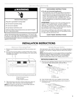
Page 5: ...an extension cord If the power supply cord is too short have a qualified electrician or serviceman install an outlet near the microwave oven SAVE THESE INSTRUCTIONS INSTALLATIONINSTRUCTIONS I 2 Remove any remaining contents from the microwave oven cavity Remove the mounting plate by peeling off the strips of tape that attach it to the back of the microwave oven and set the mounting plate aside A B...

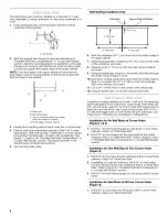
Page 6: ...of microwave oven with 2 screws removed in Step 3 of Wall Venting Installation Only earlier in this section Securely tighten screws NOTE If blower motor is not correctly oriented the 2 screws removed in Step 3 cannot be reattached to the microwave oven 7 Reattach damper plate Make sure tabs at top and back of damper plate are inserted fully into their respective slots in the microwave oven A Exhau...

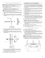
Page 7: ...ng plate No Wall Studs at Corner Holes Figure 1 No Wall Studs at Corner Holes Figure 2 A i i II i o o i I NOTE If wall stud is behind vent opening only ventless recirculating or roof venting installation can be done One Wall Stud at Two Corner Holes Figure 3 Wall Studs at All Four Corner Holes Figure 4 A A E A E i A E I I I II c c I o i_o p o i t L _ Z i I o o o o o _ o o o o 1_ 72_ooooooooooooooo...

Page 8: ...he mark made in Step 6 and mark 9 Using a straightedge draw the 2 horizontal level lines through the marks made in steps 6 and 8 10 Draw the 2 vertical plumb lines down from the marks made in Step 7 to complete the 12 x 4 30 5 x 10 2 cm rectangle This is the venting cutout area 11 Cut a 3 4 19 mm hole in one corner of the cutout area 12 Using a keyhole saw cut out the venting cutout area In additi...

Page 9: ...f Installation for One Wall Stud at Two Corner Holes in the Drill Holes in Rear Wall section 2 Start toggle nuts on the bolts from the back of the mounting plate Leave enough space for the toggle nut to go through the wall and to open 3 Position mounting plate on the wall making sure that the top of the mounting plate is aligned with the front edge of the upper cabinet 4 Push the 2 bolts with togg...

Page 10: ... assembly must be to left side of mounting plate A A Mounting plate B Mounting plate opening C Damper assembly D Long tab E Damper blade Excessive Weight Hazard Use two or more people to move and install microwave oven Failure to do so can result in back or other injury IMPORTANT The control side of the unit is the heavy side Handle the microwave oven gently 1 Place a washer on each 1 4 20 x 3 bol...

Page 11: ...r or shorter bolts are available at most hardware stores Overtightening bolts may warp the top of the microwave oven To avoid warping wood filler blocks may be added The blocks must be the same thickness as the space between the upper cabinet bottom and the microwave oven A Bolts For Roof Venting Installation Only 1 Insert damper assembly through the cabinet cutout so that the long tab of the damp...

Page 12: ...per Cabinet Template Part Number 8205924 Mounting Screw Kit includes parts A F in Parts Supplied section Part Number 8205948 2 3 4 5 Plug microwave oven into grounded 3 prong outlet Reconnect power Check the operation of microwave oven by placing 1 cup 250 mL of water on the turntable and programming a cook time of I minute at 100 power Test vent fan by touching the vent fan pad If the microwave o...

Page 13: ...al flexible Para evitar posibles dar_os al producto asegt rese de ventilar el aire hacia el exterior a menos que se trate de una instalacidn sin ducto de escape con recirculacidn No ventile el aire de escape en espacios ocultos tales come espacios dentro de paredes o techos desvanes espacios angostos o garages Para una instalacibn con ventilacibn bptima recomendamos usar cubiertas de techo o de pa...

Page 14: ... de 31 4 x 10 8 3 x 25 4 cm o un ducto de escape redondo de 6 15 2 cm La Iongitud total del sistema de ventilacidn incluyendo el ducto de escape derecho el los codo s los tubos de ajuste y las cubiertas de la pared o del piso no debera exceder del equivalente a 140 pies 42 7 m para cualquier tipo de ventilacidn Vea la seccidn Accesorios corrientes recomendados para los largos equivalentes Para un ...

Page 15: ...onectado a tierra dentro del gabinete superior Vea la seccidn Requisites electricos NOTAS Si va a instalar el horno de microondas cerca de una pared lateral izquierda asegQrese de dejar un espacio de por Io menos 6 15 2 cm entre la pared y el homo de microondas para que la puerta se pueda abrir en toda su extensidn AIgunos gabinetes y materiales de construcci6n no han sido dise_ados para resistir ...

Page 16: ...a este aparato electrodom_stico INSTRUCCIONES PARA LA CONEXl0N A TIERRA Para todos los aparatos eleetrodomesticoe de conexion con cable El homo de microondas debe estar conectado a tierra En case de que se produzca un corto circuito la conexion a tierra reduce el riesgo de electrocuci6n por medio de un alambre de escape para la corriente electrica El homo de microondas esta equipado con un cable q...

Page 17: ...ara la ventilaci6n a traves de la pared o del techo debera modificarse el sistema de ventilaci6n NOTA Saltee esta secci6n siva a usar la instalaci6n sin ducto de escape con recirculaci6n Conserve el ensamblaje de la compuerta de tiro en caso de cambiar el metodo de ventilaci6n o si va a volver a instalar el homo de microondas en otro lugar en donde pueda usar la ventilaci6n a traves de la pared o ...

Page 18: ...or del horno de microondas y los lados planes del motor del soplador queden mirando la parte posterior del homo de microondas Baje el motor del soplador nuevamente dentro del homo de microondas 6 Vuelva a sujetar el motor del soplador a la parte posterior del homo de microondas con los 2 tornillos que quit6 en el paso 3 de Solamente para la instalaci6n con ventilaci6n en la pared anteriormente en ...

Page 19: ...in pies derechos de pared en los orificios de esquina Figura 1 Sin pies derechos de pared en los orificios de esquina Figura 2 i A _ ____ A i S F i 1 D i i D A I i o i o o o Io oooooooo I iii I i i i o A _ _o _ _ o_o _ A i F I i i D i i Un pie derecho de pared en dos orificios de esquina Figura 3 NOTA Si el pie derecho de pared esta detras de la abertura del ducto de escape solamente se pedra hace...

Page 20: ... central y marque 8 Mida hacia abajo 4 10 2 cm desde la mama que hizo en el paso 6 y marque 9 Trace con una regla 2 lineas niveladas horizontales a traves de las mamas que hizo en los pasos 6 y 8 10 Trace las 2 lineas verticales a plomo hacia abajo desde las marcas hechas en el paso 7 hasta completar el rectangulo de 12 x 4 30 5 x 10 2 cm Esta es el Area de recorte de la ventilaci6n 11 Corte un or...

Page 21: ...contra el panel de yeso C A Perno de 1 4 20 x 3 B Placa de montaje C Panel de yeso D Tuerca de ajuste con resorte 5 Inserte el los tirafondos en los orificios taladrados en el los pie s derecho s de pared en el paso 2 de lnstalacidn sin pies derechos de pared en los orificios de esquina en la secci6n Taladrar orificios en la pared posterior 6 Controle la alineaci6n de la placa de montaje asegurand...

Page 22: ...suministro de energia NOTA Si el gabinete superior es de metal el forro de cable de suministro necesitara set instalado alrededor del orificio del cable de suministro como se muestra 6 A Gabinete de metal B Forro del cable de suministro de energfa Taladre orificios de 3 8 10 mm en los puntos D y E de la plantilla Estos son para los dos pernos de cabeza redonda de 1 4 20 x 3 y las arandelas usadas ...

Page 23: ...ustar el homo de microondas saltee los pasos 6 8 6 Si es necesario ajustarlo rdtelo hacia abajo Con la ayuda de 2 o mas personas levante el horno de microondas fuera de la placa de montaje y dejelo a un costado sobre una superficie protegida A Pemos Solamente para la instalacibn con ventilacibn en el techo 1 Inserte el ensamblaje de la compuerta de tiro a traves del recorte del gabinete de manera ...

Page 24: ...e instalaci6n para uso future 8205142 2005 All rights reserved Todos los derechos reservados ASlSTENCIA Llame a su distribuidor autorizado o centro de servicio Cuando Ilame usted necesitara tenet a mano el nQmero del modelo y de la serie del homo de microondas Se pueden encontrar ambos nQmeros en la placa con el nQmero de modelo y de serie que se encuentra detras de en la puerta del homo de microo...

Reviews: