


Part No. 8535840
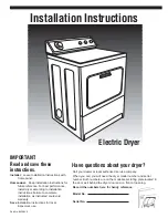
Installation Instructions
IMPORTANT:
Read and save these
instructions.
Installer: Leave Installation Instructions with
homeowner.
Homeowner: Keep Installation Instructions for
future reference. For best performance,
install dryer according to Installation
Instructions. Failure to complete
installation as instructed could void
warranty.
Save Installation Instructions for local
inspector’s use.
Have questions about your dryer?
Call your dealer or local authorized service company.
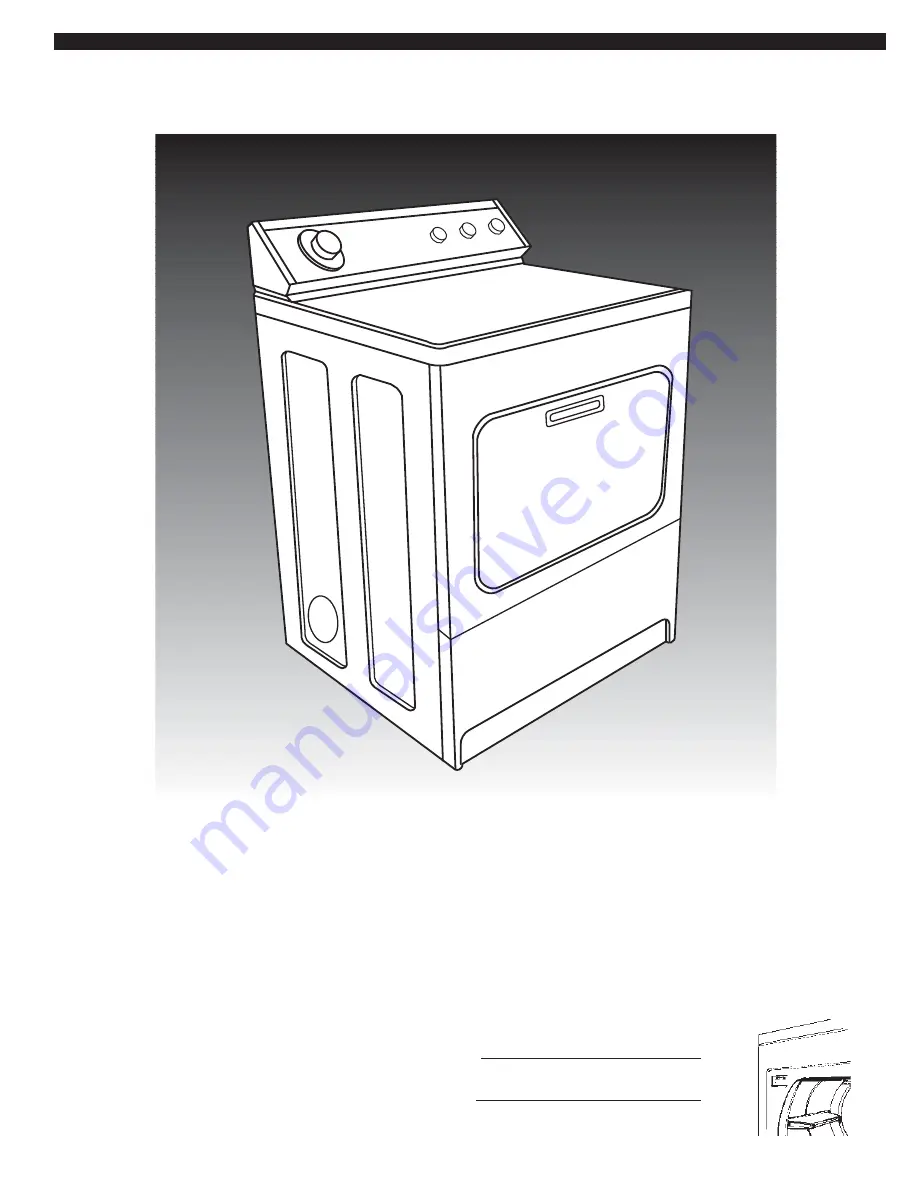
When you call, you will need the dryer model number and serial
number. Both numbers are on the model/serial rating plate located in
the door well behind the dryer door and on front of opening.
Record the numbers here for handy reference:
Model No.
Serial No.
Electric Dryer


