10
INSTALLATION INSTRUCTIONS – GAS DRYER
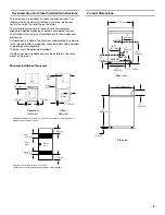
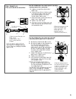
Move Dryer Into Position
NOTE:
Slide dryer onto cardboard or hardboard before moving to
avoid damaging floor covering.
1.
Using two or more people, move dryer to desired installation
location.
2.
Take tape off front corners of dryer. Open dryer and remove
the literature and parts packages. Wipe the interior of the
drum thoroughly with a damp cloth.
3.
Take two of the cardboard corners from the carton and place
them on the floor in back of the dryer. Firmly grasp the body
of the dryer and gently lay it on its back on the cardboard
corners.
4.
With one of the legs in hand, check the ridges for a diamond
marking. That's how far the leg is supposed to go into the
hole.
5.
Start to screw the leveling legs into the holes by hand.
(Use a small amount of liquid detergent to lubricate the screw
threads so it is easier to turn the legs.) Use a 1" wrench or
socket wrench to finish turning the legs until you reach the
diamond mark.
Now stand the dryer up.
6.
Remove cardboard or hardboard from under dryer.
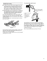
Make Gas Connection
1.
Remove red cap from gas pipe.
2.
Connect gas supply to dryer. Use pipe-joint compound
resistant to the action of L.P. gas for gas connections. If
flexible metal tubing is used, be certain there are no kinks.
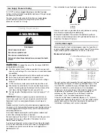
If necessary for service, open the toe panel. Use a putty knife
to press on the toe panel lock located at the center top of the
toe panel. Pull downward on the toe panel to open. Toe panel
is hinged at the bottom.
3.
Open the shutoff valve in the gas supply line.
4.
Test all connections by brushing on an approved noncorrosive
leak-detection solution. Bubbles will show a leak. Correct any
leak found.
WARNING
Excessive Weight Hazard
Use two or more people to move and install dryer.
Failure to do so can result in back or other injury.
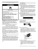
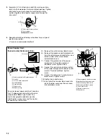
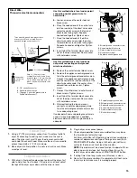
Connect Vent
1.
Using a 4" (102 mm) clamp, connect vent to exhaust outlet in
dryer. If connecting to existing vent, make sure the vent is
clean. The dryer vent must fit over the dryer exhaust outlet
and inside the exhaust hood. Make sure the vent is secured to
exhaust hood with a 4" (102 mm) clamp.
2.
Move dryer into final position. Do not crush or kink vent. Make
sure dryer is level.
3.
Check that there are no kinks in the flexible gas line.
Complete Installation
1.
With dryer in final position place level on top of the dryer, first
side to side; then front to back. If the dryer is not level, adjust
the legs of the dryer up or down until the dryer is level.
2.
Plug into a grounded 3 prong outlet.
3.
Check dryer operation (some accumulated time may be on
the timer due to factory testing).
Pull timer-set button left. (Operating time will accumulate per
number of depressions and type of timing cam used.) Push
START/RESTART button. Using a full heat cycle (not the air
cycle), let the dryer run for at least five minutes.
NOTE:
Dryer door must be closed for dryer to operate. When
door is open, dryer stops, but timer continues to run. To
restart dryer, close door and push START/RESTART button.
4.
If the burner does not ignite and you can feel no heat inside
the dryer, shut off dryer for five minutes. Check that all supply
valve controls are in “ON” position and that the electrical cord
is plugged in. Repeat five-minute test.
5.
If drying time is too long, make sure lint screen is clean.
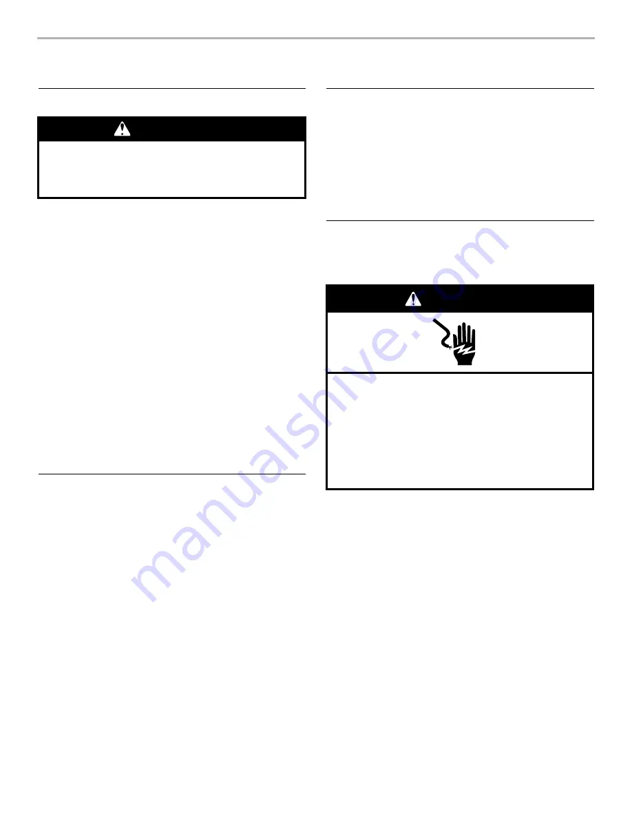
Electrical Shock Hazard
Plug into a grounded 3 prong outlet.
Do not remove ground prong.
Do not use an adapter.
Do not use an extension cord.
Failure to follow these instructions can result in death,
fire, or electrical shock.
WARNING


