5
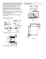
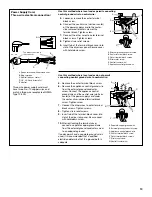
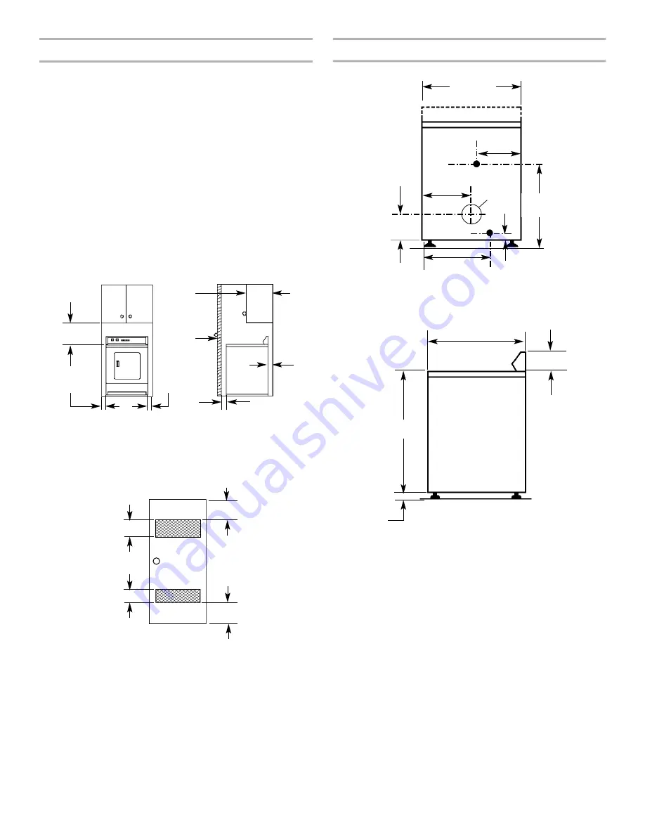
Product Dimensions
Recessed
front view
Closet
side view
Minimum Installation Clearances
*Additional clearances for wall, door and floor moldings may be required or if
external exhaust elbow is used.
Closet
door
Front
View
3" (76 mm)
3" (76 mm)
0" (0 mm)
Closet
door
14"
(356 mm)
max.
1" (25 mm)
0" (0 mm)
15"
(381 mm)*
0"
(0 mm)
29" (737 mm)
16"
(406 mm)
1"
(25 mm)
ELECTRIC
GAS
EXHAUST
4
�⁄�
"
(121 mm)
14
��⁄��
"
(371 mm)
1
�⁄�
" (32 mm)
7
�⁄�
"
(181 mm)
Back view
Side view
28
�⁄�
"
(718 mm)
18
�⁄�
"
(467 mm)
25
�⁄�
" (648 mm)
35"
(889 mm)
4"
(102 mm)
dia.
*Opening is the minimum for a closet door.
Louvered doors with equivalent air openings are acceptable.
24 in
2
(1.55 m
2
)*
48 in
2
.
(3.10 m
2
)*
4
Location Requirements
If installing a gas dryer:
IMPORTANT: Observe all governing codes and ordinances.
Check code requirements: Some codes limit or do not permit
installation of clothes dryers in garages, closets, or sleeping
quarters. Contact your local building inspector.
Make sure that lower edges of the cabinet, plus the back and
bottom sides of the dryer, are free of obstructions to permit
adequate clearance of air openings for combustion air. See
“Recessed Area and Closet Installation Instructions” below for
minimum spacing requirements.
NOTE: The dryer must not be installed in an area where it will be
exposed to water and/or weather.
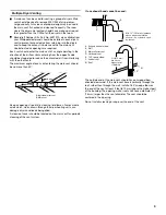
Recessed Area and Closet Installation Instructions
This dryer may be installed in a recessed area or closet. For
recessed area and closet installations, minimum clearances
can be found on the serial tag on the dryer.
The installation spacing is in inches and is the minimum
allowable. Additional spacing should be considered for ease
of installation, servicing, and compliance with local codes and
ordinances.
If closet door is installed, the minimum unobstructed air opening
in the top and bottom is required. Louvered doors with equivalent
air openings are acceptable.
The dryer must be exhausted outdoors.
No other fuel-burning appliance may be installed in the same
closet as the dryer.
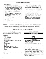
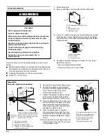
INSTALLATION REQUIREMENTS
WARNING
Explosion Hazard
Keep flammable materials and vapors, such as
gasoline, away from dryer.
Do not install in a garage.
Failure to do so can result in death, explosion, or fire.
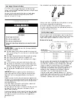
Tools and Parts
Gather the required tools and parts before starting installation.
Read and follow the instructions provided with any tools listed
here.
Tools needed
8" or 10" pipe wrench
8" or 10" adjustable wrench
Flat-blade screwdriver
Phillips screwdriver
Adjustable wrench that opens to 1" (25 mm) or hex-head
socket wrench
Level
5/16
" socket wrench
Utility knife
Vent clamps
Pipe-joint compound resistant to LP gas
Caulk gun and caulk (for installing new exhaust vent)
Pliers
Putty knife
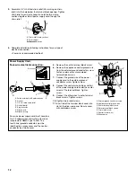
Parts supplied
Remove parts bag from dryer drum. Check that all parts were
included.
Dryer foot (4)
5
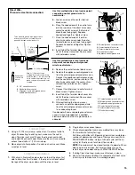
Product Dimensions
Recessed
front view
Closet
side view
Minimum Installation Clearances
*Additional clearances for wall, door and floor moldings may be required or if
external exhaust elbow is used.
Closet
door
Front
View
3" (76 mm)
3" (76 mm)
0" (0 mm)
Closet
door
14"
(356 mm)
max.
1" (25 mm)
0" (0 mm)
15"
(381 mm)*
0"
(0 mm)
29" (737 mm)
16"
(406 mm)
1"
(25 mm)
ELECTRIC
GAS
EXHAUST
4
�⁄�
"
(121 mm)
14
��⁄��
"
(371 mm)
1
�⁄�
" (32 mm)
7
�⁄�
"
(181 mm)
Back view
Side view
28
�⁄�
"
(718 mm)
18
�⁄�
"
(467 mm)
25
�⁄�
" (648 mm)
35"
(889 mm)
4"
(102 mm)
dia.
*Opening is the minimum for a closet door.
Louvered doors with equivalent air openings are acceptable.
24 in
2
(1.55 m
2
)*
48 in
2
.
(3.10 m
2
)*


