background image

8

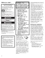
If the LOW flame needs to be
adjusted:

a. Remove the 

control knob.

b. Hold the knob

stem with a
pair of pliers.
Use a small
flat-head
screwdriver to
turn the screw located
in the center of the control knob stem
until the flame is the proper size.

c. Replace the control knob.

d. Test the flame by turning the control

from “LO” to “HI”, checking the flame
at each setting.

adjustment
screw

23.

Remove the oven rack. Remove

the oven bottom and place it on a
protected surface.

22.

Adjust the height of top burner

flames (some models).

The cooktop LOW burner flame should
be a steady blue flame approximately
1/4" (0.64 cm) high. It can be adjusted
using the adjustment screw in the center
of the valve stem. The valve stem is
located directly underneath the 
control knob.

20.

Check

the operation of
the cooktop
burners. Push in
and turn each
control knob to
the “LITE”
position. The
flame should light
within 4 seconds. The first time a burner
is lighted it may take longer than 4
seconds to light because of air in gas
line. 

19.

Remove cooktop burner caps

and grates from parts package. Align
notches in burner caps with pins in
burner base. Burner caps should be level
when properly positioned. Place burner
grates over burners and caps.

burner
grate

burner
cap

burner
base

Electronic Ignition System — 

Initial lighting and gas flame
adjustments.

Cooktop and oven burners use electronic
ignitors in place of standing pilots. When
the cooktop control knob is turned to the
“LITE” position, the system creates a
spark to light the burner. This sparking
continues, as long as control knob is
turned to “LITE”.

When the oven control is turned to the
desired setting, a glow bar heats up
bright orange and ignites the gas. No
sparking occurs and the glow bar
remains on while the burners operate.

21.

If burners do not light properly,

turn cooktop control knob to the “OFF”
position. Check that the power supply
cord is plugged in and the circuit breaker
or fuse has not blown. Check that the gas
shutoff valves are set to the “OPEN”
position. Repeat Step 18. If a burner does
not light at this point, contact your dealer
or authorized service company for
assistance.

high flame

low flame

Top burner flame appearance:

18.

Plug power supply cord into

grounded outlet.

17

. Test for gas leaks. Leak testing

shall be conducted according to the
following instructions:

Test all connections by brushing on an
approved non-corrosive leak-detection
solution. Bubbles will show a leak.
Correct any leak found.

13.

Place rack

in oven. Place level
on rack, first side to
side; then front to
back.
If the range is not
level, pull range forward until the rear
leveling leg is removed from the anti-tip
bracket. Adjust the leveling legs up or
down. Then slide range back into position.
Check that leveling leg is engaged in anti-
tip bracket.

NOTE:

Oven must be level for satisfactory

baking conditions.

pressure regulator
and valve assembly

flexible
connector

3" (7.6 cm)
connector
90° elbow

manual
shutoff valve

All connections must be wrench-
tightened.

1/2" (1.3 cm) flare union adapters

15.

Use pipe-joint compounds

appropriate for use with L.P. gas to seal
all gas connections. If flexible connectors
are used, be certain connectors are not
kinked.

16.

Open the shutoff valve in the

gas supply line. Wait a few minutes for
the gas to move through the gas line.

14.

Assemble the flexible connector

from the gas supply pipe to the pressure
regulator, located in the lower left side of
the storage drawer area, in this order:
shutoff valve, 1/2" (1.3 cm) flare union
adapter, flexible connector, 1/2" (1.3 cm)
flare union adapter. Seal all openings in
floor or wall wherever range is installed.

Summary of Contents for 9758570

Page 1: ... Part No 9758570 10 10 10 WARNING Tip Over Hazard A child or adult can tip the range and be killed Connect anti tip bracket to rear range foot Reconnect the anti tip bracket if the range is moved Failure to follow these instructions can result in death or serious burns to children and adults www whirlpool com IMPORTANT Installer Leave Installation Instructions with the homeowner Homeowner Keep Ins...

Page 2: ...e gas information label The gas information label and model serial rating plate are located on the oven frame behind the storage drawer panel Grounded electrical supply is required See Electrical requirements section Proper gas supply connection must be available See Gas supply requirements section Mobile home installation The installation of this range must conform to the Manufactured Home Constr...

Page 3: ...lded edge shaved flat 1 4 0 64 cm from each front corner of opening Tile countertops may need trim cut back 1 4 0 64 cm from each front corner and or rounded edge flattened If countertop opening width is greater than 30 3 8 77 2 cm adjust the 1 4 0 64 cm dimension Countertop must be level Place level on countertop first side to side then front to back If countertop is not level range will not be l...

Page 4: ... cm 3 3 8 85 7 cm See NOTE 10 25 4 cm 6 15 2 cm 2 1 2 6 4 cm 13 33 cm max upper cabinet depth 30 3 8 77 2 cm opening width Wall outlet to be located within the 18 x 10 45 7 cm x 25 4 cm shaded area Gas line opening to be located within either 2 1 2 x 24 6 4 cm x 61 cm shaded area Floor gas line opening if directly below regulator 25 63 5 cm countertop depth 24 61 cm base cabinet depth 36 91 4 cm c...

Page 5: ... reduced at a rate of 4 for each 1 000 feet 304 8 m above sea level Not applicable for Canada C This range is equipped for use with Natural gas It is design certified by International Approval Services I A S for Natural and L P gas with appropriate conversion Conversion to L P gas can be made using the kit included in the literature package The model serial rating plate located on the oven frame b...

Page 6: ... accordance with the National Electrical Code ANSI NFPA 70 latest edition or CSA Standard C22 1 Canadian Electrical Code Part 1 latest edition and all local codes and ordinances If a mating outlet is not available it is the personal responsibility and obligation of the customer to have a properly grounded 3 prong outlet installed by a qualified electrician 3 prong ground plug 3 prong ground type o...

Page 7: ...sure and mark a distance 25 inches 63 5 cm in from front of countertop opening and align template with mark or subtract 25 inches 63 5 cm from countertop depth and add the difference to the corresponding dimension If countertop is not flush to the side of cabinet opening align the left side of the template to allow for the countertop overhang Tape the range anti tip bracket template in place 11 Mo...

Page 8: ...ccurs and the glow bar remains on while the burners operate 21 If burners do not light properly turn cooktop control knob to the OFF position Check that the power supply cord is plugged in and the circuit breaker or fuse has not blown Check that the gas shutoff valves are set to the OPEN position Repeat Step 18 If a burner does not light at this point contact your dealer or authorized service comp...

Page 9: ...s on sides of drawer opening Lift front of drawer slightly and push firmly to close drawer To get the most efficient use from your new gas range read your Use and Care Guide Keep Installation Instructions and Guide close to the range for easy reference If flame needs to be adjusted Loosen the lock screw on the air shutter located at the rear of the broil burner Adjust the air shutter as needed Tig...

Page 10: ...ook in theYellow Pages of your telephone directory under Appliances Household Major Service and Repair or Call the Consumer Assistance Center The toll free number is listed in your Use and Care Guide When you call you will need The range model number The range serial number Both numbers are listed on the model serial rating plate located on the oven frame behind the storage drawer panel Moving the...

Reviews: