background image

INSTALLATION INSTRUCTIONS

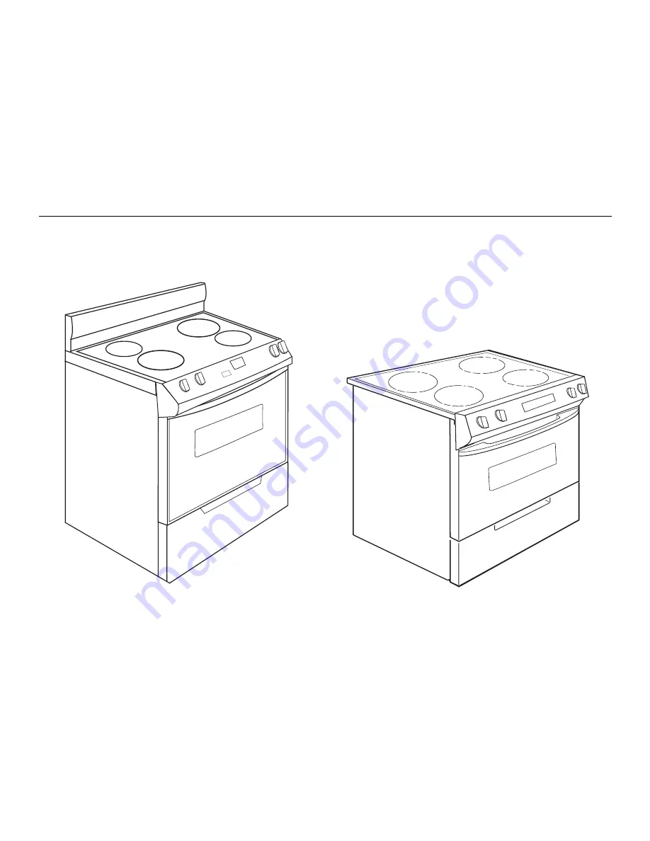
30" (76.2 CM) FREESTANDING AND SLIDE-IN

ELECTRIC RANGES 

INSTRUCTIONS POUR L’INSTALLATION

DE LA CUISINIÈRE ÉLECTRIQUE AUTOPORTANTE OU

ENCASTRABLE DE 30" (76,2 CM)

Table of Contents/Table des matières............................................................................. 2

IMPORTANT:


Save for local electrical inspector's use.

IMPORTANT :

À conserver pour consultation par l'inspecteur local des installations électriques.

9762035A

Summary of Contents for 9762035A

Page 1: ...TIONS POUR L INSTALLATION DE LA CUISINIÈRE ÉLECTRIQUE AUTOPORTANTE OU ENCASTRABLE DE 30 76 2 CM Table of Contents Table des matières 2 IMPORTANT Save for local electrical inspector s use IMPORTANT À conserver pour consultation par l inspecteur local des installations électriques 9762035A ...

Page 2: ... l emplacement de la bride antibasculement 21 Mise à niveau de la cuisinière 21 Achever l installation 22 Déplacement de la cuisinière 22 GABARIT POUR LA BRIDE ANTIBASCULEMENT 23 RANGE SAFETY You can be killed or seriously injured if you don t immediately You can be killed or seriously injured if you don t follow All safety messages will tell you what the potential hazard is tell you how to reduce...

Page 3: ...l the anti tip bracket shipped with the range see Install Anti Tip Bracket section Grounded electrical supply is required See Electrical Requirements section IMPORTANT To avoid damage to your cabinets check with your builder or cabinet supplier to make sure that the materials used will not discolor delaminate or sustain other damage This oven has been designed in accordance with the requirements o...

Page 4: ...protrudes 1 4 8 cm beyond 24 61 cm base cabinet A 7 20 cm B 30 76 2 cm C 43 111 4 cm overall height with leveling legs screwed all the way in D 36 91 4 cm cooktop trim height with leveling legs screwed all the way in E 30 76 2 cm F 27 68 6 cm max from handle to standoff at back of range G Model serial number plate located on the right hand side oven door trim A B C D E F G A 35 90 5 cm overall hei...

Page 5: ...nless steel 0 024 0 6 mm aluminum or 0 020 0 5 mm copper 30 76 2 cm minimum clearance between the top of the cooking platform and the bottom of an unprotected wood or metal cabinet A 13 33 cm upper cabinet depth B 30 76 2 cm min opening width C For minimum clearance to the top of the cooktop see NOTE D 30 76 2 cm min opening width E Junction box 8 20 3 cm to 22 55 9 cm from either cabinet 7 17 8 c...

Page 6: ... breaker box through flexible or nonmetallic sheathed copper or aluminum cable See Electrical Connection Allow 2 to 3 ft 61 0 cm to 91 4 cm of slack in the line so that the range can be moved if servicing is ever necessary A UL listed conduit connector must be provided at each end of the power supply cable at the range and at the junction box Wire sizes and connections must conform with the rating...

Page 7: ...rtified Power Cord intended to be plugged into a standard 14 50R wall receptacle Be sure the wall receptacle is within reach of range s final location Do not use an extension cord CountertopPreparation forSlide inRangesOnly The cooktop sides of the slide in range fit over the cutout edge of your countertop If you have a square finish flat countertop and the opening width is 30 76 2 cm no counterto...

Page 8: ...e sliding range into its final position check that the anti tip bracket will slide under the range and onto the rear leveling leg prior to anti tip bracket installation InstallAnti TipBracket Contact a qualified floor covering installer for the best procedure for drilling mounting holes through your type of floor covering Before moving range slide range onto shipping base cardboard or hardboard 1 ...

Page 9: ...SpacerCover forSlide inRangesOnly If you are installing a slide in range into an existing freestanding range opening you may use the rear spacer cover to fill in the opening at rear of range To order see the Assistance or Service section of the Use and Care Guide or contact the dealer from whom you purchased the range Using the screws provided with the kit attach the rear spacer cover to the sides...

Page 10: ... needed for the flexible conduit connection Assemble a UL listed conduit connector in the opening Feed the flexible conduit behind the black horizontal cross brace and through the strain relief allowing enough slack to easily attach the wiring to the terminal block Tighten strain relief screw against the flexible conduit 4 Complete installation following instructions for your type of electrical co...

Page 11: ...screws from the aluminum terminal blocks 2 Connect the neutral center wire to the center terminal connector using one of the hex washer head screws Securely tighten screw for proper electrical connection 3 Connect the other 2 wires lines 1 and 2 to the outer terminal screws on the terminal block 4 Tighten strain relief screws 5 Replace terminal block cover If your home has And you will be connecti...

Page 12: ...nk away from the range so that it does not contact the range 2 Connect the bare ground wire to the range using the ground link screw and cup washer The ground wire must be attached first and must not contact any other terminal 3 Loosen do not remove the hex washer head screw and insert the neutral white wire under the screw clamp at the bottom of the center position terminal connector 4 Insert the...

Page 13: ...secure the range to the floor Any method of securing the range is adequate as long as it conforms to the standards in the Location Requirements section LevelRange 1 Place rack in oven Place level on rack and check levelness of range first side to side then front to back If range is not level pull range forward until rear leveling leg is removed from the anti tip bracket On Ranges Equipped with Sto...

Page 14: ...qualified technician MovingtheRange When moving range slide range onto cardboard or hardboard to avoid damaging the floor covering If removing the range is necessary for cleaning or maintenance For power supply cord connected ranges 1 Unplug the power supply cord 2 Slide range forward to complete cleaning or maintenance 3 Check that anti tip bracket is installed Look for the anti tip bracket secur...

Page 15: ...ssurez vous de toujours lire tous les messages de sécurité et de vous y conformer AVERTISSEMENT DANGER Voici le symbole d alerte de sécurité Ce symbole d alerte de sécurité vous signale les dangers potentiels de décès et de blessures graves à vous et à d autres Tous les messages de sécurité suivront le symbole d alerte de sécurité et le mot DANGER ou AVERTISSEMENT Ces mots signifient Risque de bas...

Page 16: ...pédiée avec la cuisinière voir la section Installation de la bride antibasculement Une source d électricité avec liaison à la terre est nécessaire Voir la section Spécifications électriques IMPORTANT Pour éviter tout dommage consulter le constructeur ou le fabricant du placard pour déterminer si les matériaux utilisés ne subiront pas un changement de couleur une déstratification ou d autres dommag...

Page 17: ...our sera en saillie de 1 4 8 cm au delà de la base des placards de 24 61 cm A 7 20 cm B 30 76 2 cm C 43 111 4 cm Hauteur totale avec les pieds de nivellement complètement abaissés D 36 91 4 cm Hauteur de la garniture de la table de cuisson avec les pieds de nivellement complètement abaissés E 30 76 2 cm F 27 68 6 cm Longueur maximale de la poignée au support à l arrière de la cuisinière G Plaque s...

Page 18: ...minium 0 024 0 6 mm ou cuivre 0 020 0 5 mm Distance de séparation de 30 76 2 cm ou plus entre le dessus de la table de cuisson et le fond d un placard de bois ou de métal non protégé A Profondeur des placards supérieurs 13 33 cm B Largeur de l ouverture 30 76 2 cm min C Pour la distance libre minimale vers la partie supérieure de la table de cuisson voir la REMARQUE D Largeur de l ouverture 30 76 ...

Page 19: ...il a été réalisé par moulage il sera nécesaire de réaliser une surface plane de 1 cm dans chaque angle avant de l ouverture Il peut être nécessaire de tailler le carrelage du plan de travail sur 1 cm sur chaque angle à l avant et ou d aplanir un bord arrondi Si la largeur de l espace disponible dans le plan de travail est de plus de 30 76 2 cm ajuster la dimension de 1 cm Il faut que le plan de tr...

Page 20: ...thodes de perçage des trous de montage à travers le revêtement de sol existant Avant de déplacer la cuisinière la faire glisser sur sa base d expédition un carton ou un panneau de fibres dur 1 Enlever le gabarit de la trousse de la bride antibasculement à l intérieur de la cavité du four ou de la couverture arrière du présent manuel 2 Placer le gabarit sur le sol dans l ouverture du placard de sor...

Page 21: ...rificationdel emplacement delabrideantibasculement 1 Ouvrir le tiroir jusqu à la première position de butée Soulever l avant du tiroir pour dégager les roulettes blanches des glissières du tiroir Retirer le tiroir et le poser sur une surface protégée 2 Vérifier l installation de la bride antibasculement Vérifier que la bride antibasculement est solidement fixée au sol Faire glisser la cuisinière v...

Page 22: ...oncteur ouvert Cuisinière branchée sur une prise de courant Circuit d alimentation sous tension Consulter la section Dépannage dans le Guide d utilisation et d entretien Après 5 minutes de fonctionnement de la cuisinière vérifier l échauffement Si elle est froide éteindre la cuisinière et contacter un technicien qualifié Déplacementdelacuisinière Lorsqu on déplace la cuisinière la faire glisser su...

Page 23: ...BASCULEMENT Cut here and place top edge against the left side cabinet and right edge against rear wall Couper ici et placer le rebord supérieur contre le côté gauche du placard et le rebord droit contre la paroi arrière Trous dans la bride Holes in bracket ...

Page 24: ...9762035A 2007 All rights reserved Tous droits réservés 7 07 Printed in U S A Imprimé aux É U ...

Reviews: