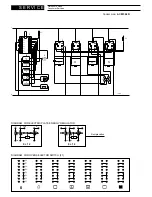
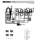
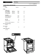

S E R V I C E
Whirlpool Europe
Consumer Services
Date
15.01.2001
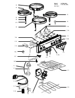
Spare part list
for Electric Cooker
Model
ACM 394 N
Version
8576 394 32000
Service Nr.
00/0000-00 00
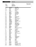
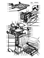
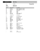
Pos. No.
Spare Part No.
Denomination
2.1
355VC6120
Glass with frame
2.3
001138
Screw
2.6
51B6113
Hotplates support
2.13
103572
Rear spacing
2.14
211022
Pivot
2.15
003060
Snap ring
4.1
4506N1SV11
Oven body
4.4
030082.1
Oven insulation
4.5
030081.1
Rear insulation
4.6
094354DX
Rear right coupler
4.7
094354SX
Rear left coupler
4.8
4116108
Rear panel
4.9
4216107Z
Upper shelter
4.10
103028
Shim
4.11
040011
Buffer
4.13
053039
Seal
4.14
094333DX
Front right coupler
4.15
094333SX
Front left coupler
4.18
103160035
Base panel
4.20
081074
Buffer
4.22
094371
Drawer fixing bracket
4.23
39E6N013
Drawer front panel
4.24
39K6103Y
Drawer
4.25
36C6ND13
Right side panel
4.26
36C6NS13
Left side panel
4.32
4219604Z
Rear insulation support
4.34
103338DX/E
Right rail
4.35
103338SX/E
Left rail
4.36
103338DX/I
Right drawer rail
4.37
103338SX/I
Left drawer rail
4.38
0810
83035
Right front trim plug
4.39
0810
84035
Left front trim plug
4.43
51B6107
Rail drawer support
4.44
053074
Top/bottom seal
4.45
079017
Tangential fan
4.46
46A6N03Z
Air conveyor
4.47
46A6N02Z
Funnel
4.48
68061005
Plinth
4.52
094325
Stainless steel child lock hook
4.53
094153
Anti-tilt bracket
5.1
032612046
Door glass
5.3
037207035
Door handle
5.4
4116111
Handle bar
5.6
001183
Screw
5.8
063096
Door hinge (male)
5.9
063066
Door hinge (female)
5.10
373FF713K
Door panel
5.11
053084
Gasket
5.12
0311000.1T
Inner glass (Thermovit)
5.14
214021
Nut
5.15
001214
Screw
5.16
003035
Washer
5.17
103205.1
Washer
5.21
003041
Washer
5.23
51B5616
Inner glass support
5.25
040056
Third glass rubber
5.26
0312039
Third glass
5.27
103418035
Child lock knob
5.29
68061002
Child lock
5.30
001209
Screw
5.31
035093
Spring
5.32
003052
Ring
5.33
214054
Nut M5
7.1
217436
Shelf support
7.3
48B6101K
Oven tray
7.4
217220
Oven shelf
7.13
48EF702K
Pastry plate
8.19
030083.1
Bottom element insulation
8.20
4216102Z
Bottom element support
8.23
47AN601K
Fan diffuser
8.42
51BF702
Thermostat bulb protection


