S E R V I C E
Whirlpool Europe
Consumer Services
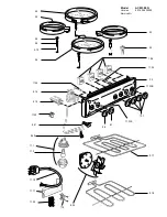
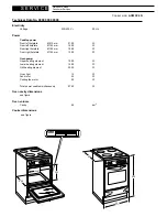
Cooker mod. ACM 394 N
1
6
4
3
8
2
7
5
P1
P6
P4
P3
P8
P2
P7
P5
°
C
TM
C
G
S
LF
V
CF
TL
S1
F1
1131261
5
4
3
2
1
M
S2
T
F2
P1
F4
P3
F3
P2
F5
P4
CR
S1
S2
4
P1
P2
PILOT
2
S1
S2
4
P1
P2
PILOT
2
S1
S2
4
P1
P2
PILOT
2
S1
S2
4
P1
P2
PILOT
2
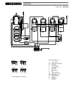
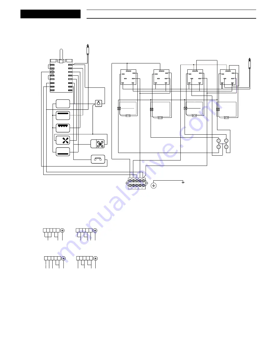
THIS APPLIANCE MUST BE EARTHED
PE
N
L1 L2 L3
L2
L1
N PE
400V 3N
1 2 3
5
4
1 2 3
5
4
L1
N PE
230V
400V 2N
L3
L1 L2
PE
230V -V3
1 2 3
5
4
1 2 3
5
4
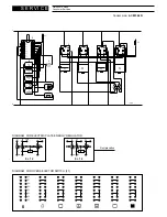
ELECTRIC DIAGRAM KEY
F1
Oven commutator
F2/5
Radiant heater commutators
LF
Oven lamp
TM
Oven thermostat
TL
Oven thermolimitator
C
Top element
G
Grill element
S
Bottom element
V
Fan
S1
Thermostat pilot lamp
S2
Electric plate pilot lamp
P1/P4 Radiant heaters
CR
Residual heat lamps
CF
Cooling fan
M
Terminal block
T
Earth plant


