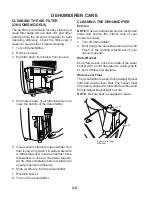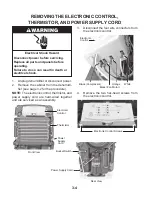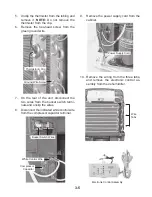
3-1
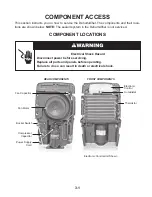
COMPONENT LOCATIONS
This section instructs you on how to service the Dehumidifier. The components and their loca-
tions are shown below.
NOTE:
The sealed system in the Dehumidifier is not serviced.
COMPONENT ACCESS
Electronic
Control
FRONT COMPONENTS
Thermistor
Fan Capacitor
Fan Motor
Bucket Switch
Compressor
Capacitor
REAR COMPONENTS
Electronic Control Unit Shown
Power Supply
Cord
Humidistat
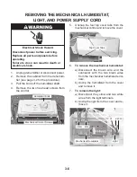
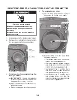
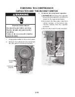
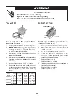
Electrical Shock Hazard
Disconnect power before servicing.
Replace all parts and panels before operating.
Failure to do so can result in death or electrical shock.
Summary of Contents for AD25BSS
Page 4: ... iv NOTES ...
Page 8: ...1 4 NOTES ...
Page 28: ...3 12 NOTES ...
Page 33: ...6 1 WIRING DIAGRAM 1 WIRING DIAGRAMS ...
Page 34: ...6 2 WIRING DIAGRAM 2 ...
Page 35: ...6 3 WIRING DIAGRAM 3 ...
Page 36: ...6 4 NOTES ...
Page 37: ...6 5 NOTES ...
Page 38: ...6 6 NOTES ...
Page 40: ...CORPORATION ...

