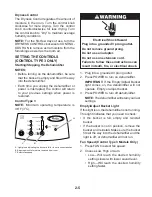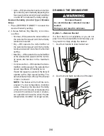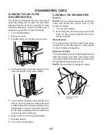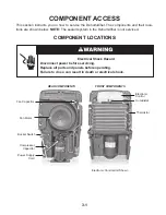
3-5
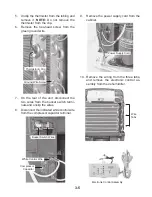
Wire
Tabs
10. Remove the wiring from the three tabs,
and remove the electronic control as-
sembly from the dehumidifier.
5. Unclip the thermistor from the tubing and
remove it.
NOTE:
Do not remove the
thermistor from the clip.
6. Remove the hex-head screw from the
green ground wire.
9. Remove the power supply cord from the
cabinet.
Thermistor & Clip
7. On the rear of the unit, disconnect the
two wires from the bucket switch termi-
nals and unclip the wires.
8. Disconnect the indicated white control wire
from the compressor capacitor terminal.
Ground Wire Screw
White Control Wire
Bucket Switch Wires
Electronic Control Assembly
Compressor
Capacitor
Power Supply Cord
Summary of Contents for AD25BSS
Page 4: ... iv NOTES ...
Page 8: ...1 4 NOTES ...
Page 28: ...3 12 NOTES ...
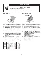
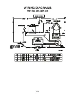
Page 33: ...6 1 WIRING DIAGRAM 1 WIRING DIAGRAMS ...
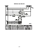
Page 34: ...6 2 WIRING DIAGRAM 2 ...
Page 35: ...6 3 WIRING DIAGRAM 3 ...
Page 36: ...6 4 NOTES ...
Page 37: ...6 5 NOTES ...
Page 38: ...6 6 NOTES ...
Page 40: ...CORPORATION ...

