background image

3-6

REMOVING THE MECHANICAL HUMIDISTAT, 

LIGHT, AND POWER SUPPLY CORD

Electrical Shock Hazard

Disconnect power before servicing.
Replace all parts and panels before    
operating.
Failure to do so can result in death or 
electrical shock.

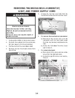
1.  Unplug dehumidifier or disconnect power.
2.  Remove the cabinet from the dehumidi-

fier (see page 3-2 for the procedure).

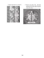
3.  Pull the knob off the humidistat shaft. 
4.  Remove  the  two  hex-head  screws  from 

the control. 

5.  Unsnap  the  four  top  cover  tabs  from  the 

mechanical control and remove the cover.

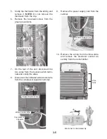
  Mechanical Control Screws

  Humidistat Knob

  Top Cover Tabs

6. 

To remove the mechanical humidistat: 

a) Disconnect  the  brown  wire  and  the 

connector  with  the  two  black  wires 
from the mechanical humidistat termi-
nals.

b) Unclip  the  humidistat  from  the  cover 

and remove it.

7. 

To remove the light: 

a) Disconnect  the  yellow  and  two  white 

wires from the light terminals.

b) Unclip the light from the cover and re-

move it.

  Mechanical Humidistat

  Light

  2 BK     BN 

  YL     2 WH 

Summary of Contents for AD25BSS

Page 1: ...CONSUMER SERVICES TECHNICAL EDUCATION GROUP PRESENTS R 103 JOB AID Part No 8178563 DEHUMIDIFIERS Models AD25BSS AD35DSS AD50DSS Models AD35USS AD50USS AD70USS ...

Page 2: ...ams used in this Job Aid are typical and should be used for training purposes only Always use the Wiring Diagram supplied with the product when servicing the unit GOALS AND OBJECTIVES The goal of this Job Aid is to provide information that will enable the service technician to prop erly diagnose malfunctions and repair the dehumidifier The objectives of this Job Aid are to Understand and follow pr...

Page 3: ...ions 3 1 Removing The Cabinet 3 2 Removing The Electronic Control Thermistor And Power Supply Cord 3 4 Removing The Mechanical Humidistat Light And Power Supply Cord 3 6 Removing The Fan Capacitor And The Fan Motor 3 8 Removing The Compressor Capacitor And The Bucket Switch 3 10 COMPONENT TESTING 4 1 Mechanical Humidistat 4 1 Fan Capacitor Compressor Capacitor 4 1 Fan Motor 4 2 Bucket Switch 4 2 D...

Page 4: ... iv NOTES ...

Page 5: ...rds that can kill or hurt you and others All safety messages will follow the safety alert symbol and either the word DANGER or WARNING These words mean All safety messages will tell you what the potential hazard is tell you how to reduce the chance of injury and tell you what can happen if the instructions are not followed You can be killed or seriously injured if you don t immediately follow inst...

Page 6: ...l Std Deicer 1 Speed Fan D Electromechanical Std Deicer 2 Speed Fan U Electronic Ultra Low Temp Application 2 Speed Fan MODEL SERIES S Estar B No Estar YEAR OF INTRODUCTION S 2006 T 2007 ENGINEERING CHANGE DIGITS 0 1 Etc MODEL SERIAL NUMBER DESIGNATIONS MODEL NUMBER SERIAL NUMBER SERIAL NUMBER Q S 21 00043 MANUFACTURING SITE Q LaVergne TN YEAR OF PRODUCTION S 2005 WEEK OF PRODUCTION 21st Week PROD...

Page 7: ...1 3 MODEL SERIAL NUMBER AND WIRING DIAGRAM LABEL LOCATIONS Model Serial Number Label Behind Water Bucket Wiring Diagram Label Inside Front Half Of Cabinet ...

Page 8: ...1 4 NOTES ...

Page 9: ...d moisture from the air and maintain relative humidity at acceptable levels A dehumidifier does not remove all of the moisture from the air as this is not necessary or desirable The dryness control on the dehumidifier allows the customer to adjust a variable humidistat to control the relative humidity of room air Once the humidistat is set to maintain acceptable humidity levels in a room the dehumid...

Page 10: ...ed below 65 F Mechanical control models with a deicer thermostat i e AD35DSS may be operated as low as 55 F Electronic control models i e AD35USS monitor the temperature of the evaporator us ing a thermistor and may be operated as low as 38 F When the thermistor reaches 30 F the control begins timing After 10 minutes at or below 30 F the compressor is turned off The fan continues to run for a peri...

Page 11: ...red relative humidity the compressor and fan will be cycled back on If the relative humidity has not increased the unit will only run for 3 minutes There is a 3 minute minimum on or off time used to protect the compressor that requires at least 3 minutes of run time or off time before the compressor stops or restarts The reason for the compressor to be turned on 30 minutes after it cycles off is t...

Page 12: ...lows indicating the bucket is full or is not in correct position B Adjusts amount of moisture removed from room C Selects fan speed A C B 1 Plug into a grounded 3 prong outlet 2 To turn on dehumidifier turn DRYNESS CONTROL clockwise IMPORTANT If the Empty Adjust Bucket light comes on the dehumidifier will not operate Empty or adjust bucket 3 To turn off dehumidifier turn DRYNESS CONTROL counterclockw...

Page 13: ...n adapter Do not use an extension cord Failure to follow these instructions can result in death fire or electrical shock A Light glows indicating the bucket is full or is not in correct position B Adjusts amount of moisture removed from room C Selects fan speed A B C 1 Plug into a grounded 3 prong outlet 2 Press POWER to turn on dehumidifier IMPORTANT If the Empty Adjust Bucket light comes on the de...

Page 14: ...l setting Max Dry Will operate the dehumidifier at the selected fan speed until the humid ity levels are lowered to the maximum level Continuous Run Will operate the dehu midifier continuously at the selected fan speed regardless of humidity level If Auto fan speed is selected the fan will operate at the High speed setting The dehumidifier will turn off only if the bucket is full or removed NOTE The ...

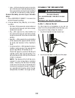
Page 15: ...r on the inside of the dehumidifier Hand tighten 4 Place the other end of garden hose into a floor drain Check to see that the hose lies flat and is in the drain 5 Reinstall bucket A Garden hose B Drain hose connector B A NOTES To use the bucket without the garden hose remove the garden hose Then reinstall bucket The bucket must be installed and properly aligned for the dehumidifier to operate with or...

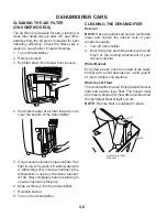
Page 16: ...ners Air dry filter completely before replacing to ensure maximum efficiency 6 Slide air filter up into the dehumidifier 7 Reinstall bucket 8 Turn on the dehumidifier CLEANING THE DEHUMIDIFIER Exterior NOTE Have an authorized service technician clean and service the interior coils of your product annually 1 Turn off dehumidifier 2 Dust front grille and side panels with a soft brush or the dusting attach...

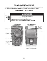
Page 17: ...ier is not serviced COMPONENT ACCESS Electronic Control FRONT COMPONENTS Thermistor Fan Capacitor Fan Motor Bucket Switch Compressor Capacitor REAR COMPONENTS Electronic Control Unit Shown Power Supply Cord Humidistat Electrical Shock Hazard Disconnect power before servicing Replace all parts and panels before operating Failure to do so can result in death or electrical shock ...

Page 18: ...trical shock 1 Unplug dehumidifier or disconnect power 2 Pull the water bucket out of the dehumidi fier and remove it 3 If present pull the air filter down and out from behind the front louvers 4 Remove the two front screws from the front half of the cabinet Water Bucket Front Screws 5 Remove the screw from the left and right side of the cabinet Left Side Screw Air Filter ...

Page 19: ...ottom screw and the two top hex head screws from the rear half of the cabinet 7 Pull the front and rear halves of the cabi net from the dehumidifier and remove them Bottom Rear Screw Top Rear Screws Front Half Rear Half ...

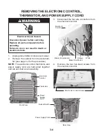
Page 20: ...et from the dehumidi fier see page 3 2 for the procedure NOTE The electronic control thermistor and power supply cord are hard wired together and are serviced as an assembly Electronic Control Thermistor 3 Disconnect the four wire connectors from the electronic control Power Supply Cord Black Compressor Black Fan Motor Orange White Electronic Control 4 Remove the two hex head screws from the elect...

Page 21: ...move the hex head screw from the green ground wire 9 Remove the power supply cord from the cabinet Thermistor Clip 7 On the rear of the unit disconnect the two wires from the bucket switch termi nals and unclip the wires 8 Disconnect the indicated white control wire from the compressor capacitor terminal Ground Wire Screw White Control Wire Bucket Switch Wires Electronic Control Assembly Compresso...

Page 22: ...shaft 4 Remove the two hex head screws from the control 5 Unsnap the four top cover tabs from the mechanical control and remove the cover Mechanical Control Screws Humidistat Knob Top Cover Tabs 6 To remove the mechanical humidistat a Disconnect the brown wire and the connector with the two black wires from the mechanical humidistat termi nals b Unclip the humidistat from the cover and remove it 7...

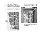
Page 23: ...b Disconnect the black power supply cord wire from the COM terminal of the bucket switch Bucket Switch BK COM Wire WH Wire Power Supply Cord c Remove the hex head screw from the green ground wire at the top of the condenser Condenser Ground Wire Screw d Remove the power supply cord from the dehumidifier Compressor Capacitor ...

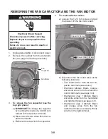
Page 24: ...pacitor terminals b Disconnect the two wires from the ca pacitor terminals c Remove the screw from the capacitor b Disconnect the fan motor wires at the following locations Two brown wires from the fan ca pacitor terminals see above Electronic Models Black orange and white wires from the electronic control terminals see page 3 4 Mechanical Type 1 Models Black and white wires from the humidistat an...

Page 25: ... Remove the three 5 16 hex head screws from the fan motor then pull the wiring out of the access hole and remove the motor Fan Motor Screws Top green ground wire on condenser Top Ground Wire Screw Condenser ...

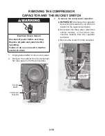
Page 26: ...ower 2 Remove the cabinet from the dehumidi fier see page 3 2 for the procedure Bucket Switch Compressor Capacitor 3 To remove the compressor capacitor a IMPORTANT Discharge the capacitor by touching the leads of a 20 000 ohm resistor to the capacitor terminals b Disconnect the three wires electronic control models or four wires me chanical models from the capacitor terminals c Remove the screw fr...

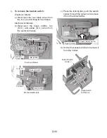
Page 27: ...nd yellow N C wires from the switch terminals Bucket Switch BK COM BK N C Electronic Model Mechanical Models TN N O BK COM YL N C Bucket Switch Press Tab Push In c Press the locking tab push the switch holder through the cutout and remove it from the dehumidifier Switch Holder d Unclip the bucket switch and remove it from the holder Unclip Switch To Remove Bucket Switch Holder ...

Page 28: ...3 12 NOTES ...

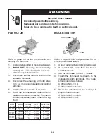
Page 29: ...the compressor capacitor 1 Unplug dehumidifier or disconnect power 2 IMPORTANT Discharge the capacitor by touching the leads of a 20 000 ohm resis tor to the capacitor terminals 3 Disconnect the wires from the capacitor terminals 4 Set the ohmmeter to the R x 1K scale 5 Touch the ohmmeter test leads to the ca pacitor terminals The meter should indi cate several ohms and gradually return to infinit...

Page 30: ... servicing Replace all parts and panels before operating Failure to do so can result in death or electrical shock BUCKET SWITCH Refer to page 3 10 for the procedure for ac cessing the bucket switch 1 Unplug dehumidifier or disconnect power 2 Disconnect the wires from the bucket switch terminals 3 Set the ohmmeter to the R x 1 scale 4 Touch the ohmmeter test leads to the indicated switch terminals ...

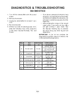
Page 31: ...r button 2 Remove the bucket 3 Unplug the dehumidifier for at least 1 sec ond 4 Reconnect power 5 Within 5 seconds of restoring power com plete the following 3 key entry sequence in this order Desired Humidity Fan and Power If you press a wrong key during the 3 key sequence or if more than 5 seconds elap ses before completing the sequence you will need to restart the sequence from the beginning Aft...

Page 32: ...tive 3 Check both components and replace if defective 4 Compressor windings open 4 Check continuity and replace if one or both windings are open Fan does not run compressor runs 1 Fan motor not getting power 1 Check wiring Repair or replace as necessary 2 Fan motor defective 2 Replace fan motor 3 Fan blade jammed 3 Remove obstruction Replace if fan blade is damaged Fan and compressor run evaporato...

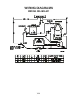
Page 33: ...6 1 WIRING DIAGRAM 1 WIRING DIAGRAMS ...

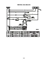
Page 34: ...6 2 WIRING DIAGRAM 2 ...

Page 35: ...6 3 WIRING DIAGRAM 3 ...

Page 36: ...6 4 NOTES ...

Page 37: ...6 5 NOTES ...

Page 38: ...6 6 NOTES ...

Page 39: ...RIZED SERVICER IN CANADA FOR PRODUCT SPECIFICATIONS AND WARRANTY INFORMATION CALL 1 800 461 5681 FOR TECHNICAL ASSISTANCE WHILE AT THE CUSTOMER S HOME CALL THE TECHNICALASSISTANCE LINE 1 800 488 4791 HAVE YOUR STORE NUMBER READY TO IDENTIFY YOU AS AN AUTHORIZED SERVICER FOR WHIRLPOOL PRODUCTS 1 800 253 1301 FOR KITCHENAID PRODUCTS 1 800 422 1230 FOR ROPER PRODUCTS 1 800 447 6737 FOR LITERATURE ORD...

Page 40: ...CORPORATION ...

Reviews: