3-8
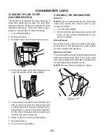
Fan
Capacitor
Fan Motor
REMOVING THE FAN CAPACITOR AND THE FAN MOTOR
Electrical Shock Hazard
Disconnect power before servicing.
Replace all parts and panels before
operating.
Failure to do so can result in death or
electrical shock.
1. Unplug dehumidifier or disconnect power.
2. Remove the cabinet from the dehumidi-
fier (see page 3-2 for the procedure).
3.
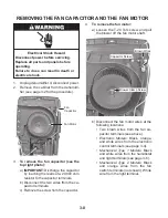
To remove the fan capacitor (see the
top right photo):
a)
IMPORTANT:
Discharge the capacitor
by touching the leads of a 20,000 ohm
resistor to the capacitor terminals.
b) Disconnect the two wires from the ca-
pacitor terminals.
c) Remove the screw from the capacitor.
b) Disconnect the fan motor wires at the
following locations:
Two brown wires from the fan ca-
pacitor terminals (see above).
Electronic Models:
Black, orange,
and white wires from the electronic
control terminals (see page 3-4).
Mechanical Type 1 Models:
Black
and white wires from the humidistat
and light terminals (see page 3-6).
Mechanical Type 2 Models:
Black
and orange wires from the fan
switch terminals (not shown). White
wire from the light terminal.
•
•
•
•
Blower Clamp Screw
Brown Wires
Capacitor Screw
4.
To remove the fan motor:
a) Loosen the T-20 Torx screw and pull
the blower off the fan motor shaft.
Summary of Contents for AD25BSS
Page 4: ... iv NOTES ...
Page 8: ...1 4 NOTES ...
Page 28: ...3 12 NOTES ...
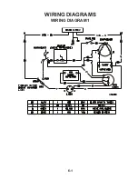
Page 33: ...6 1 WIRING DIAGRAM 1 WIRING DIAGRAMS ...
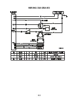
Page 34: ...6 2 WIRING DIAGRAM 2 ...
Page 35: ...6 3 WIRING DIAGRAM 3 ...
Page 36: ...6 4 NOTES ...
Page 37: ...6 5 NOTES ...
Page 38: ...6 6 NOTES ...
Page 40: ...CORPORATION ...

