4-1
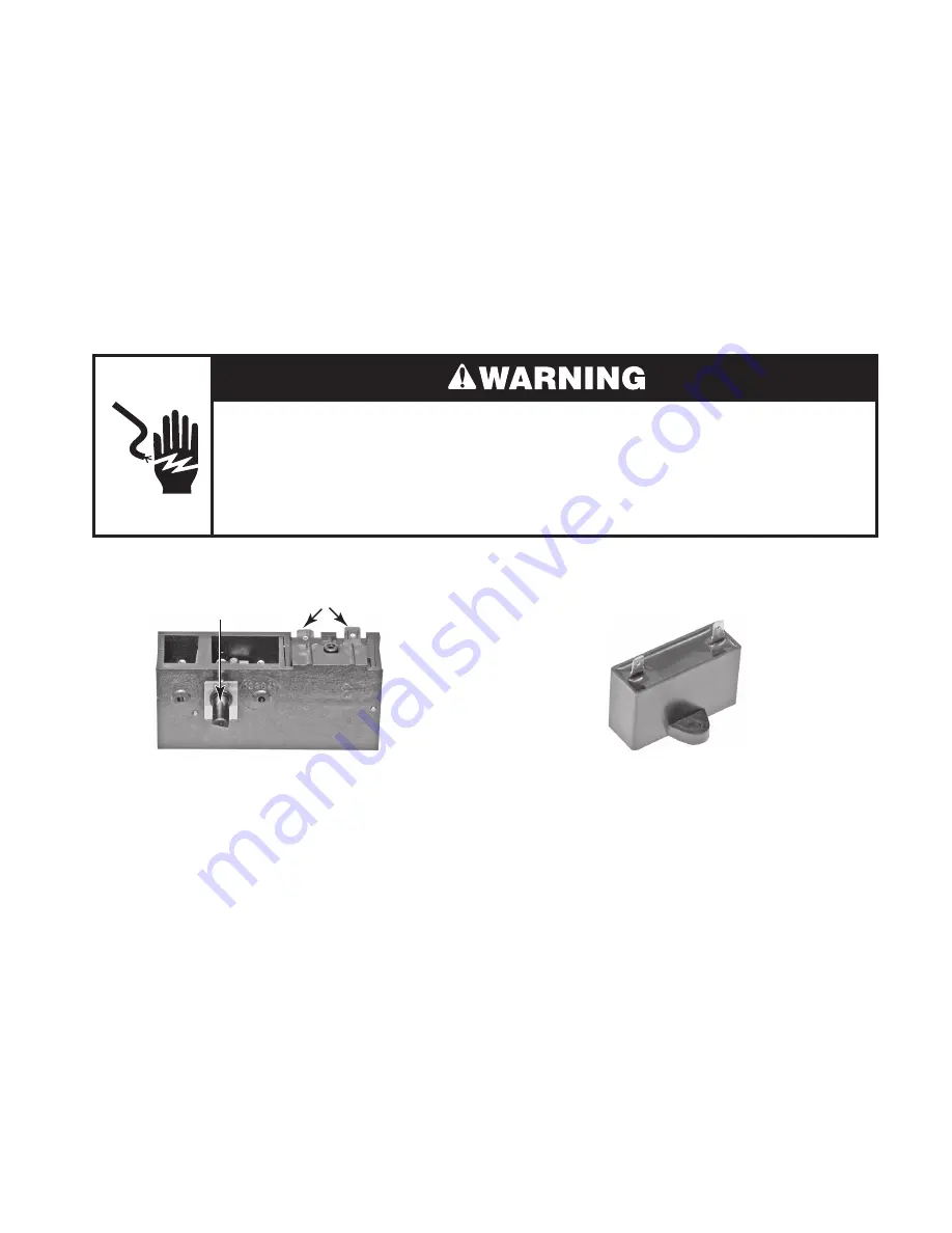
COMPONENT TESTING
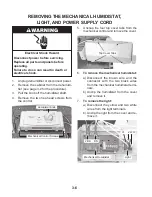
Refer to page 3-6 for the procedure for ac-
cessing the mechanical humidistat.
1. Unplug dehumidifier or disconnect power.
2. Disconnect the two wires from the hu-
midistat terminals.
3. Turn the humidistat control fully counter-
clockwise.
4. Set the ohmmeter to the R x 1 scale.
5. Touch the ohmmeter test leads to the hu-
midistat terminals. The meter should indi-
cate an open circuit (infinite).
6. Turn the humidistat control clockwise un-
til you hear it click. The meter should in-
dicate a closed circuit (0 Ω).
MECHANICAL HUMIDISTAT
Electrical Shock Hazard
Disconnect power before servicing.
Replace all parts and panels before operating.
Failure to do so can result in death or electrical shock.
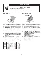
FAN CAPACITOR &
COMPRESSOR CAPACITOR
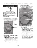
Refer to pages 3-8 and 3-10 for the proce-
dures for accessing the fan capacitor and the
compressor capacitor.
1. Unplug dehumidifier or disconnect power.
2.
IMPORTANT:
Discharge the capacitor by
touching the leads of a 20,000 ohm resis-
tor to the capacitor terminals.
3. Disconnect the wires from the capacitor
terminals.
4. Set the ohmmeter to the R x 1K scale.
5. Touch the ohmmeter test leads to the ca-
pacitor terminals. The meter should indi-
cate several ohms, and gradually return
to infinity.
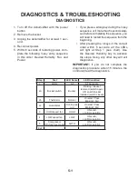
Before testing any of the components, per-
form the following checks:
The most common cause for control failure
is corrosion on connectors. Therefore, dis-
connecting and reconnecting wires will be
necessary throughout test procedures.
All tests/checks should be made with a
VOM or DVM having a sensitivity of 20,000
ohms-per-volt DC, or greater.
•
•
Check all connections before replacing
components, looking for broken or loose
wires, failed terminals, or wires not pressed
into connectors far enough.
Resistance checks must be made with
power cord unplugged from outlet, and
with wiring harness or connectors discon-
•
•
Terminals
Control
Summary of Contents for AD25BSS
Page 4: ... iv NOTES ...
Page 8: ...1 4 NOTES ...
Page 28: ...3 12 NOTES ...
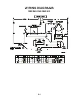
Page 33: ...6 1 WIRING DIAGRAM 1 WIRING DIAGRAMS ...
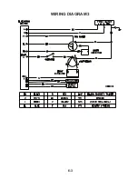
Page 34: ...6 2 WIRING DIAGRAM 2 ...
Page 35: ...6 3 WIRING DIAGRAM 3 ...
Page 36: ...6 4 NOTES ...
Page 37: ...6 5 NOTES ...
Page 38: ...6 6 NOTES ...
Page 40: ...CORPORATION ...


