4-2
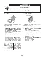
Refer to page 3-8 for the procedure for ac-
cessing the fan motor.
1. Unplug dehumidifier or disconnect power.
2.
IMPORTANT:
Discharge the capacitor by
touching the leads of a 20,000 ohm resis-
tor to the capacitor terminals.
3. Disconnect the fan motor wires from the
capacitor terminals.
4. Disconnect the remaining fan motor wires
from the mechanical or electronic control
terminals.
5. Set the ohmmeter to the R x 1 scale.
6. Touch the ohmmeter test leads to the in-
dicated motor wire connectors. The meter
should indicate as shown in the following
chart:
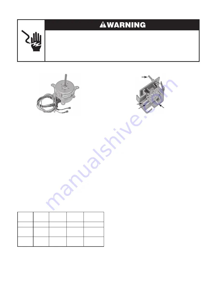
FAN MOTOR
Electrical Shock Hazard
Disconnect power before servicing.
Replace all parts and panels before operating.
Failure to do so can result in death or electrical shock.
BUCKET SWITCH
Refer to page 3-10 for the procedure for ac-
cessing the bucket switch.
1. Unplug dehumidifier or disconnect power.
2. Disconnect the wires from the bucket
switch terminals.
3. Set the ohmmeter to the R x 1 scale.
4. Touch the ohmmeter test leads to the
indicated switch terminals. The meter
should indicate as follows:
COM and N.C. = 0 Ω
COM and N.O. = Infinite
5. Press the actuator and the readings in
step 4 should reverse:
COM and N.C. = infinite
COM and N.O. = 0 Ω
Actuator
COM
N.O.
N.C.
1188411
1188413
Motor Motor Capacity
Test
Resistance
Part # Type
(Pints)
Lead
(Ohms)
1188409 1-Speed 25
Wh-Bk
161 ±20%
2-Speed 35 & 50
Wh-Or 142 ±20%
2-Speed 35 & 50
Wh-Bk
118 ±20%
2-Speed 70
Wh-Or 65 ±20%
2-Speed 70
Wh-Bk
50 ±20%
Summary of Contents for AD25BSS
Page 4: ... iv NOTES ...
Page 8: ...1 4 NOTES ...
Page 28: ...3 12 NOTES ...
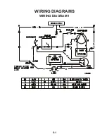
Page 33: ...6 1 WIRING DIAGRAM 1 WIRING DIAGRAMS ...
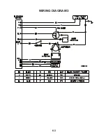
Page 34: ...6 2 WIRING DIAGRAM 2 ...
Page 35: ...6 3 WIRING DIAGRAM 3 ...
Page 36: ...6 4 NOTES ...
Page 37: ...6 5 NOTES ...
Page 38: ...6 6 NOTES ...
Page 40: ...CORPORATION ...

