5 - SET-UP FOR OPERATION
0802_GB_42
- GAS KITCHENS
04/2008
5.2 Maintenance
Attention! Before doing any repair or maintenance
work, unplug the appliance.
The following maintenance program should be carried out at least
once a year by qualified personnel with license:
• Check that all the safety and adjustment devices are working
properly;
• Check that the burners are working properly with regard to:
- ignition
- combustion safety;
Check functioning of the appliance as described in paragraph 5.1.6
“Operation control”.
If it should be necessary to clean the open flame burners, proceed as
follows:
• Remove the grills, the flame spreaders and the bodies of the bur-
ners;
• Clean the parts with water and detergent and an appropriate
tool. Rinse and dry.
When reassembling the parts, make sure you place them back in the
right position.
5.3 Replacing parts
All parts must be replaced by authorized technicians
only!
To replace the following parts first remove all the control knobs and
control panel (after loosening the fixing screws), then extract the
ignition wire.
5.3.1 Open flame gas cock
Loosen the fitting of the pipes (pos. 9 fig. 1) of the gas, unfix the
graft (pos. 8 fig. 1) of the thermocouple, unscrew the two screws
(pos. 6 fig. 1) fixing the cock on the gas piping through the hanger
(pos. 7 fig. 1) and replace the piece (pos. 17 fig. 1) install in reverse
order install paying attention to the seal ring. After the replacement
check the seal using a leack detetctor spray.
5.3.2 Open flame gas burner
Remove with the help of a screwdriver the spring (pos. 18 fig. 1)
blocking the gas pipe and slip off it from burner seat, unscrew the
screws (pos. 12 fig. 1) fixing the injector-holder cup (pos. 4 fig. 1), pull
down the cup, unfix the thermocouple and the plug (pos. 11 and 15 fig.
1) and replace the piece install in reverse order. After replacement, check
injector, see table 1 and do a seal check using a leak detector spray.
5.3.3 Open flame thermocouple
Unfix the graft (pos. 8 fig. 1) fixing the thermocouple on the cock,
unscrew the screws (pos. 12 fig. 1) fixing the injector-holder cup
(pos. 4 fig. 1), pull down the cup, unfix the thermocouple (pos. 11
fig. 1) and replace the piece install in reverse order.
5.3.4 Open flame plug
Unfix the cable (pos. 16 fig. 1) from the piezo ignition, unscrew the
screws (pos. 12 fig. 1) fixing the injector-holder cup (pos. 4 fig. 1),
pull down the cup, unfix the plug (pos. 15 fig. 1) and replace the
piece install in reverse order.
After any maintenance or repair work, replace the con-
trol panel and the lower panel.
After replacing gas input components, check operation
again and test for leakage.
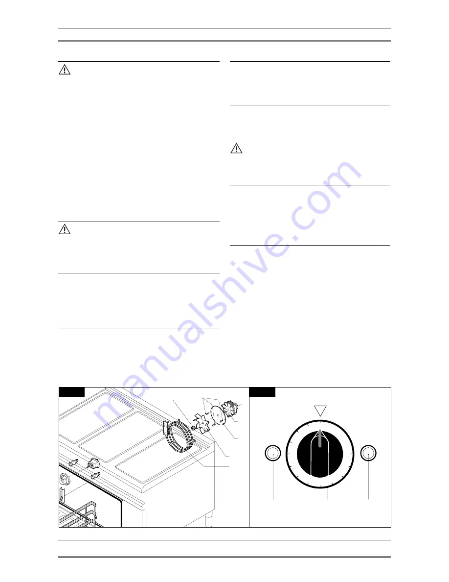
5.3.5 Heating element of electric oven GN 1/1
Unplug the appliance from the electrical mains!
To remove the heating element (pos. 6 fig. 2), remove the rear bulk-
head, unscrew the screws fixing the the heating element to the
oven, pull the heating elementforward with relative wires.
Disconnect the wires, and install a new heating element in reverse
order.
5.3.6 Fan of of electric oven GN 1/1
Unplug the appliance from the electrical mains!
To replace the fan remove the back unscrew the sight screws, discon-
nect the wires from the motor, from the inside of the chamber
remove the rear bulkhead fan cover and the fan (pos. 1 fig. 2) by
loosening the locking nut (pos. 2 fig. 2 “NB. the nut is with left
thread”).
Loosen the bolts (pos. 3 fig. 2) hat hold the motor (pos. 4 fig. 2) on
the oven and pull off from rear. Re-install in reverse order position-
ing in the correct way the seal protection (pos. 5 fig. 2) and power
mains.
11
· 16
1
4
5
6
2
3
3
2
1
0
50
100
150
200
250
300
Fig. 2
Fig. 2A


