


5.1 Preparation and Start-up
Before starting up the appliance, remove the protective wrapping.
Then carefully clean the working surface and the external parts with
lukewarm water and detergent, using a damp rag to remove all traces
of anti-rust material applied in the factory, then dry with a clean cloth.
5.1.1 Start-up
Before starting up the appliance, check that its specifications (cate-
gory and type of gas used) match those of the family and group of
the gas available locally.
If not, it is necessary to adapt the appliance to the gas family or
group required (see paragraph 5.1.10 “Conversion and adaptation”).
To start up the appliance, see the instructions for regular use.
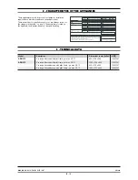
5.1.2 Check of power
The appliances must be used with the specific injectors for the nomi-
nal power.
The power may be:
• the nominal power indicated on the data plate of the appliance;
• the reduced capacity power.
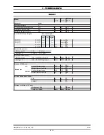
These injectors are shown in table 1.
Nominal power is also obtained in respect of the supply pressure:
• from 15 to 22.5 mbar for gases of the second family (G20/methane)
• from 25 to 45 mbar for gases of the 3rd family
(G30/butane, G31/propane)
The appliance shall not be operated outside the above-mentioned
pressure ranges.
To adjust power with reduced capacity, use the data in table 1.
If you wish to further check the nominal power, you may do so by
using a gas meter according to the so-called "volumetric method".
A simple inspection is usually enough to check if injectors are func-
tioning correctly.
5.1.3 Checking the input pressure
Input pressure should be measured using a fluid measuring gauge
(e.g. a gooseneck pipe, min. resolution 0.1 mbar).
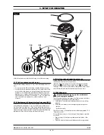
Remove lock screw (pos. 22 fig. 1) from the pressure intake tube and
connect the gauge hose: once measurement is complete, replace the
screw and do a seal check using a leak detector spray.
5.1.4 Power check with volumetric method
Using a gas meter and a stopwatch, you can read the volume of gas
output per time unit. The correct volume corresponds to the value
"E" expressed in litres/hour (l/h) or litre/minute (l/min).
The following formula is used to calculate the value of “E”:
It is important measure the power when the appliance is in standby
status.
The calorific power value can be requested from the local gas company.
The nominal power and the minimum power with respect to the
nominal pressure are obtained by consulting the table for the
adjustment of the gas passage (table 1).
WARNING
There is no pre-adjustment device for the nominal
power.
E =
Power
Operating calorific value
5.1.5 Power check for operation with liquid gas
Check if the type of injectors used meet the data of the table 1.
Check that the pressure reducer installed in the system has an outlet
pressure which is compliant with paragraph 5.1.2 "Check of power"
(can be checked on the data plate of the appliance or on the table
1).
5.1.6 Operation control
• Start the appliance in accordance with the instructions.
• Check that the appliance does not have any leaks by using a
leak-detecting spray.
• Check ignition and that flame on the main burner lights pro-
perly and is correctly formed, even on low.
• A servicing and maintenance contract is recommended.
5.1.7 Check of pilot flame
For proper regulation, the pilot flame must surround the thermo-
couple and it must have a perfect appearance; otherwise, check gas
pressure, make sure the injector is clean and has the right diameter
for the gas, see table 1.
5.1.8 Checking the primary air
Both the oven and the open flames are equipped with primary air
adjustment. Air volume flow is correct when there is sufficient pro-
tection against the flame rising when the burner is cold or in case of
flashback when the burner is hot. See table 1.
5.1.9 Operator training
• Explain and show the user how the machine works according to
the instructions, and hand him this manual.
• Remind the user that any structural alterations or any building
modification or renovation may affect the combustion air supply,
thus requiring a second operation check.
5.1.10 Conversion and adjustment
To change over form one kind of gas to another, for example from
methane to liquid gas, or to another type of gas, the use of suitable
injectors for the main burner is required, in accordance with the
table 1.
The injectors of the main burners and pilot for different types of
gas, marked with the relative diameter in hundredths of mm, are in
an envelope which is provided with the appliance. If injectors are
not available please contact the factory with model and serial num-
ber written on technical data sticker. After transformation or adap-
tation, carry out operating checks as described in paragraph 5.1.6
“Operation control”.
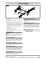
5.1.11 Replacing of open burners injectors
To replace the injector (pos. 1 fig. 1): remove the grill, the flame
spreader and the burner body.
Then unscrew the screw (pos. 2 fig. 1), which secures the primary air
bushing (pos. 3 fig. 1), ), move air regulation screwing it in to make
the injector accessible, replace the injector with one able for the
type of gas, see table 1, reinstall everything in reverse order.
After fitting the new injectors, reset primary air distance “A” (fig. 1)
see table 1, and fasten the bushing with the appropriate screw.
After the replacement check the seal using a leack detector spray.
5.1.12 Replacement of pilot injectors of open flames
To replace the injector (pos. 12 fig. 1): remove the grill, he flame
spreader and the burner body.
Unscrew the screws (pos. 18 fig. 1), fixing the pilot on the the injec-
tor-holder cup, lift up the pilot to a more convenient position for
unscrew the nut (pos. 11 fig. 1), pull down the nut together the
pipe and the bicone (pos. 13 fig. 1) unfix the injector and replace
the injector with one able for the type of gas, see table 1, install in
reverse order.
5 - SET-UP FOR OPERATION
0813_GB_42
- GAS KITCHENS WITH PILOT
04/2008
8
· 16