background image

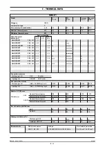
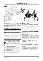
5.1 Preparation and Start-up

Before starting up the appliance, remove the protective wrapping.

Then carefully clean the working surface and the external parts with
lukewarm water and detergent, using a damp rag to remove all traces
of anti-rust material applied in the factory, then dry with a clean cloth.

5.1.1 Start-up

Before starting up the appliance, check that its specifications (cate-
gory and type of gas used) match those of the family and group of
the gas available locally. 

If not, it is necessary to adapt the appliance to the gas family or
group required (see paragraph “Conversion and adjustment”).  

To start up the appliance, see the instructions for regular use.  

5.1.2 Check of power

The appliances must be used with the specific nozzles for the nomi-
nal power.  

The power may be:  

•  the nominal power indicated on the data plate of the appliance;

•  the reduced capacity power.  

These nozzles are shown in table 1 “Technical data”.

Nominal power is also obtained in respect of the supply pressure:

•  from 15 to 22.5 mbar for gases of the second family (G20/methane)

•  from 25 to 45 mbar for gases of the 3rd family 

(G30/propane, G31/butane) 

The appliance shall not be operated outside the above-mentioned
pressure ranges. 

To adjust power with reduced capacity, use the data in table 1. 

If you wish to further check the nominal power, you may do so by
using a gas meter according to the so-called "volumetric method".  

A simple inspection is usually enough to check if nozzles are func-
tioning correctly. 

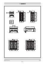
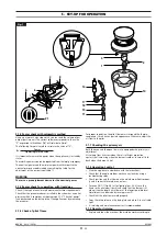
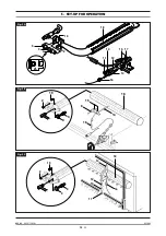
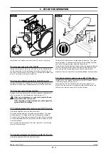
5.1.3 Checking the input pressure (Fig. 1) 

Input pressure should be measured using a fluid measuring gauge
(e.g. a gooseneck pipe, min. resolution 0.1 mbar).

Remove lock screw (22) from the pressure intake tube and connect the
gauge hose: once measurement is complete, replace the screw (22).

4 - ISTRUZIONI PER LA MESSA IN OPERA

5 - SET-UP FOR OPERATION

063_03

- GAS KITCHENS

10

· 22

03/2006

If the type of gas indicated on the data plate of the appliance does
not correspond to the gas which is present, refer to the paragraph
"Conversion and adaptation". 

4.3.2 Statutory regulations and technical requirements

During installation of the appliance, the following regulations must
be adhered to:

•  Relevant legal directives;

•  Local building and combustion regulations;

•  "Technical rules for gas systems" worksheet;

•  "Technical rules for liquid gas" worksheet;

•  “Gas installations in industrial kitchens” worksheet;

•  Relative accident prevention standards;

•  Local gas utility regulations.

•  Local building and fire codes.

4.3.3 Installation

Assembly, installation and maintenance, i.e.:   

assembly, gas connection, check of power, conversion or adapta-
tion and start-up; 

Ask for approval from the local gas company.

4.3.4 Installation operations 

To level the appliance correctly, adjust the height of the feet.

4.3.5 Gas connection

The R 3/4” gas connection of the appliance to the gas pipeline can
either be permanently fixed to the mains or made detachable using
an approved cock.    

If hoses are used, they must be in stainless steel and in compliance
with the DIN 3383, part 1 or DIN 3384 regulations. 

After completing gas connection, check for leaks using a special
leak-detector spray.

4.3.6 Smoke extraction

These kitchens are type A appliances, thus no smoke extraction sys-
tem is required.

For the ventilation of the room where the appliance is installed,
refer to related legislation.

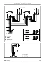
4.3.7 Electrical connection

Before connecting the unit to the mains, check that:  

•  The mains voltage corresponds to the values shown on the data

plate; 

•  The earth is in working order;

•  The power cord is suitable to the electrical input of  the appli-

ance (see table 1 on page  8).  

Also, up the line from the unit, there must be a device with contact
opening of at least 3 mm which makes it possible to disconnect the
appliance in omnipolar mode.  

To this end, for example, safety contactors may be used.  

The omnipolar switch must be located near the appliance and be
readily accessible.  

The power cord must be approved and have a section which is suit-
able for the appliance. 

The cord must be at least type H07 RN-F.

4.3.8 Equipotential

The appliance must be hooked up to a unipotential system.  The
required terminal is located near the cord inlet.  

It is marked by a tag with a symbol

.

Summary of Contents for AGB 350/WP

Page 1: ...063_03 Instructions for installation use and maintenance 03 2006 GAS KITCHENS AGB 350 WP AGB 352 WP AGB 353 WP AGB 351 WP AGB 354 WP AGB 358 WP AGB 359 WP AGB 360 WP AGB 361 WP AGB 362 WP AGB 363 WP ...

Page 2: ...CHARACTERISTICS 063_03 GAS KITCHENS 2 22 03 2006 Supplied by Date Customer Service FAX e mail ...

Page 3: ...AXI 13 5 1 16 Replacement of nozzle of gas ovens GN 1 1 and MAXI 13 5 1 17 Replacement of burner nozzle gas oven 13 5 2 Maintenance 13 5 3 Replacing parts 14 5 3 1 Gas valve open flames 14 5 3 2 Thermocouple open flames 14 5 3 3 Plug gas oven 14 5 3 4 Gas valve gas oven 14 5 3 5 Thermocouple gas oven 14 5 3 6 Main burner gas oven 14 5 3 7 Heating elements electric oven GN 1 1 14 5 3 8 Heating elem...

Page 4: ... AGB 352 WP AGB 350 WP AGB 351 WP AGB 350 WP AGB 351 WP AGB 352 WP AGB 352 WP 800 694 53 53 21 21 3 4 220 680 255 350 295 310 590 3 4 220 680 255 350 295 310 590 3 4 200 200 400 200 200 400 220 680 255 350 295 310 590 3 4 9 5 kW 9 5 kW 9 5 kW 4 0 kW 9 5 kW 9 5 kW 9 5 kW 9 5 kW 4 0 kW Ø 100 mm 9 5 kW Ø 125 mm ...

Page 5: ... 200 200 400 900 255 350 295 140 140 255 200 200 295 350 310 590 AGB 360 WP AGB 361 WP AGB 360 WP AGB 361 WP AGB 358 WP AGB 358 WP AGB 359 WP AGB 360 WP 9 5 kW 4 0 kW 140 255 200 200 295 350 310 590 AGB 359 WP 9 5 kW 9 5 kW 9 5 kW 9 5 kW 9 5 kW 4 0 kW 200 200 400 900 255 350 295 140 AGB 361 WP 9 5 kW 9 5 kW 9 5 kW 9 5 kW ...

Page 6: ... 55 340 900 255 296 350 200 200 400 400 140 AGB 362 363 WP AGB 362 363 WP AGB 362 WP AGB 353 WP AGB 354 WP 9 5 kW 9 5 kW 9 5 kW 4 0 kW 4 0 kW 9 5 kW 900 255 296 350 200 200 400 400 140 AGB 363 WP 9 5 kW 9 5 kW 9 5 kW 9 5 kW 9 5 kW 9 5 kW 9 5 kW 9 5 kW 9 5 kW 4 0 kW 4 0 kW 9 5 kW AGB 353 WP AGB 354 WP AGB 353 WP AGB 354 WP 680 255 296 350 310 590 200 200 400 400 3 4 220 ...

Page 7: ...900 x 270 340 800 x 900 x 900 970 800 x 900 x 900 970 1200 x 900 x 900 970 1200 x 900 x 900 970 Nr 51BQ2899 51BQ2899 51BQ2899 51BQ2899 51BQ2899 51BQ2899 51BQ2899 0051 TIPO TYPE CAT KAT GAS GAZ G30 G31 G20 G25 II2H3B P P mbar 30 30 20 II2H3 P mbar 30 37 20 II2H3 P mbar 28 37 20 II2L3B P P mbar 30 30 25 II2ELL3B P P mbar 50 50 20 20 II2E 3 P mbar 28 37 20 25 II2H3B P P mbar 50 50 20 I2E P mbar 20 II...

Page 8: ...kW kW X Ø 100 8 0 4 0 1 2 ZW Ø 125 23 9 5 3 9 Gas oven GN 2 1 16 0 7 8 Gas oven MAXI 24 0 12 0 145 Adjustable 100 45 225 Adjustable 150 108 215 140 270 170 No of nozzles pilot burner G20 G30 G31 27 19 27 19 35 20 36 19 Electrical data Electric oven power GN 2 1 5 9 kW Voltage V AC 400 3N 50 Hz AC 230 3 50 Hz No of cables per section 5 x 2 5 mm2 4 x 2 5 mm2 Overall thermal power gas AGB 358 WP AGB ...

Page 9: ... adjustment of the oven temperature which can be varied between 160 and 300 C is made with the thermostat The bottom of the oven in cast iron with reinforced ribs for GN 2 1 and steel for MAXI is in two pieces The smoke collector is in aluminised sheet metal and the protection grill is in enamelled cast iron Gas version GN 1 1 ventilated The tubular burners are in stainless steel and are resistant...

Page 10: ...ph Conversion and adaptation 4 3 2 Statutory regulations and technical requirements During installation of the appliance the following regulations must be adhered to Relevant legal directives Local building and combustion regulations Technical rules for gas systems worksheet Technical rules for liquid gas worksheet Gas installations in industrial kitchens worksheet Relative accident prevention sta...

Page 11: ...ilot flame Power Operating calorific value E For proper regulation the pilot flame must surround the thermo couple and it must have a perfect appearance Otherwise adjust the air flow to the pilot 5 1 7 Checking the primary air Both the oven and the open flames are equipped with primary air adjustment Air volume flow is correct when there is sufficient protection against the flame rising when the b...

Page 12: ...5 SET UP FOR OPERATION 063_03 GAS KITCHENS 12 22 03 2006 18 6 14 16 15 3 9 19 2 Fig 2B A 15 14 2 9 19 11 12 13 17 3 4 16 18 Fig 2A 18 14 12 13 11 16 3 9 19 2 Fig 2C ...

Page 13: ... Replace the injector 12 see the table TECHNICAL DATA and replace all parts in reverse order 5 1 16 Replacement of pilot nozzle for gas oven GN 2 1 Fig 2A Remove the lower panel as previously described Remove the fas tening screw 2 of the primary air bushing 4 and push the bushing into the venturi tube The nozzle 3 is now easily accessible After substituting the nozzle based on the type of gas and...

Page 14: ... heating element is attached to the top of the cooking chamber To remove the heating elements loosen the screws that attach them to the corresponding flange and pull the heating elements and rela tive wires forward Use a screwdriver to disconnect the wires and install a new heating element in reverse order 5 3 8 Heating elements for electric oven GN 1 1 Fig 4B Unplug the appliance from the electri...

Page 15: ... see fits though without changing its essential features The manufacturer declines all responsibility for any non compliance with the provisions contained in this manu al 6 2 Start up 6 2 1 Lighting and shutting off open flame burner Fig 1 Turn the knob of the desired burner 21 to the spark position Press all the way down and use a match or other suitable instrument to light the pilot burner Hold ...

Page 16: ...us position with the fan on convection In this position the top heating element from above and the bottom heating element from below are on and at the same time the fan is in operation convection Position 2 3 4 5 6 7 MAX Degrees C 160 175 190 210 230 260 300 Convection cooking In this position heat is produced by a circular heating ele ment located on the back of the oven around the fan Defrost fu...

Page 17: ...ce generally losing its inactive coat The inactive layer can be chemically damaged or jeopardized by reducing agents oxygen consumption if they come in contact with the steel concentrated or at high temperatures These active sub stances include for instance saline and sulphurous substances chlorides salts concentrated spices such as mustard vinegar essences soup cubes kitchen salt solutions etc Mo...

Page 18: ...t collection centre or returned to the reseller when buying a new equivalent item of equipment The user is responsible for delivering the unit at the end of its life to the appropriate collection facilities Failure to do so shall result in the user being subject to the penalties prescri bed by the legislation in force on waste Suitable separated collection so that the unit no longer used can be se...

Page 19: ...6 7 2 P3 P4 P5 P6 P1 P2 1 3 4 C R G RC RG MV RV RS T RG RS RV MV T Grill heating element Bottom heating element Fan heating element Motorized fan Thermostat A C R G RC Terminal board Commutator Green indicator light Green indicator light Top heating element Grill heating element ...

Page 20: ... F1 B2 P3 5 P4 6 P6 P5 P2 7 2 1 3 4 1 3 5 2 4 6 1 3 5 2 4 6 R2 R1 H1 H2 F2 230 V 3 14 75 A 1 3 5 2 4 6 R1 R2 230 V 25 7 A 1 3 5 2 4 6 R1 R2 L1 N 1 mA 2 3 4 1 mA 2 3 4 L1 L2 L3 90101 H1 H2 R1 2 F2 Indicator light power indicator light heating Oven heating element Temperature limiter mA B1 B2 F1 Terminal Switch Selector Thermostat Connected power 5 9 kW 230 400 ...

Page 21: ...n Indicator light mA B1 F1 F2 H1 H2 R1 R2 Terminal board Switch Thermostat Temperature limiter Green indicator light Orange indicator light Upper heating elements Lower heating elements 3 2 1 0 B2 5 P3 P5 P4 P2 P6 6 7 2 1 3 4 230 V 3 14 75 A 1 3 5 2 4 6 R1 R2 230 V 25 7 A 1 3 5 2 4 6 R1 R2 L1 N 1 mA 2 3 4 1 mA 2 3 4 L1 L2 L3 ...

Page 22: ...NG OR PRINTING ERRORS DUE TO ITS POLICY OF CONTINUAL PRODUCT IMPROVEMENT THE MANUFACTURER RESERVES THE RIGHT TO MAKE ANY CHANGES DEEMED NECESSARY THE MANUFACTURER CANNOT BE HELD RESPONSIBLE IF THE INSTRUCTIONS CONTAINED IN THIS MANUAL ARE NOT OBSERVED THIS DOCUMENTATION IS ONLY INTENDED FOR QUALIFIED TECHNICIANS WHO ARE AWARE OF THE RESPECTIVE SAFETY REGULATIONS ...

Reviews: