Instruction AGS 646-WP- rev9 english
ed.05
Page 13 di 15
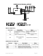
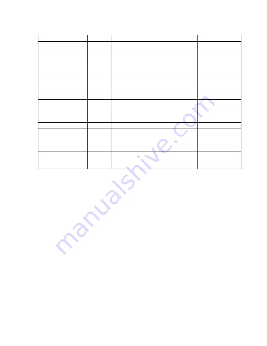
POWER CONNECTIONS
Terminal Name
Description
Notes
CN5-1
RS1
Common contact
Controlo relay for upper resistor
Max. capacity 10A
CN5-2
RS2
Normally Open contact
Control relay for upper resistor
Max. capacity 10A
CN5-3
RI1
Common contact control relay for
lower resistor
Max. capacity 10A
CN6-1
RI2
Normally Open contact
Control relay for lower resistor
Max. capacity 10A
CN6-2
V12
Control relay NO contact
Upper and lower fans [RL3]
Max. capacity 1A
CN6-3
V3
Control relay NO contact for air
recirculation fan [RL4]
Max. capacity 1A
CN7-1
LMP
Control relay NO contact for oven
interior light [RL5]
Max. capacity 1A
CN7-2 UMD
--
Not
connected
CN7-3 --
-- Not
connected
CN8-1
L
Phase 230Vac supplying circuit board
+ common contact for relays RL3,
RL4, RL5 and RL6.
Max. capacity 1A
CN8-2
N
Neutral 230Vac supplying circuit
board
Max. capacity 1A
CN8-3 PE
Earth
connection
--
RL3 :
Key board cooling fan connection (12V + and -) – until serial no. 205280399.
RL6 :
connection clutch for key board cooling fan (12 V + and -) – from serial no. 205280400.
TEST MODE AND THERMOCOUPLE CONFIGURATION
AUTO-TEST
Short-circuit contact CN9 on the back of the circuit board using a jumper.
The following functions will be available while CN9 is short-circuited:
-
The relays will be activated cyclically, one at a time.
-
The parts of the display will be lit up, one at a time.
-
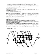
Press button 8 (fig. 2) + for the upper zone temperature (SW1) to light up the three upper
parts of the upper zone temperature display.
-
Press button 8 (fig. 2) - for the upper zone temperature (SW2) to light up the three lower
parts of the upper zone temperature display.
-
Press button 9 (fig. 2) + for the lower zone temperature (SW3) to light up the three upper
parts of the lower zone temperature display.
-
Press button 9 (fig. 2) - for the lower zone temperature (SW4) to light up the three lower
parts of the lower zone temperature display.
-
Press button 7 (fig. 2) + for the timer (SW5) to light up the three upper parts of the timer
display.
-
Press button 7 (fig. 2) - for the timer (SW6) to light up the three lower parts of the timer
display.
-
Press START/STOP button 6 (fig. 2) for the timer (SW10) to light up the three centre parts
of the timer display.
-
Press ON/OFF (SW9) button 1 (fig. 2) to light up the centre parts of all displays.


