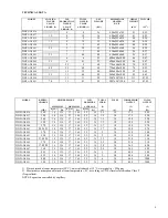
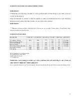
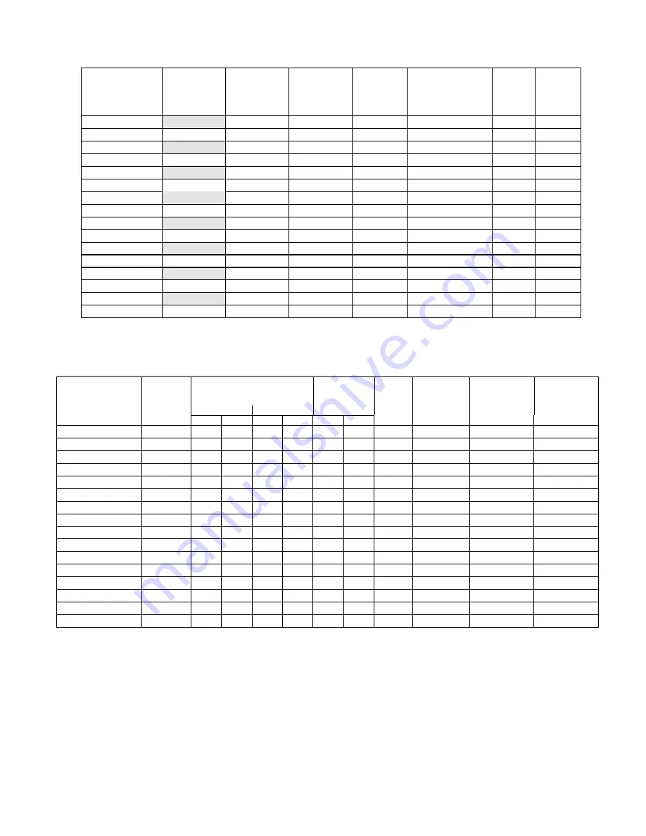
background image


9

TECHNICAL DATA 


MODEL 


COOLING 

WATER 

USAGE  

L/HOUR  (1) 

ICE 

PRODUCTION 

WATER 

USAGE 

L/HOUR  (1) 

TOTAL 

WATER 

USAGE 

L/HOUR (1) 

NET 

WEIGHT 


(KG) 

DIMENSIONS 

CRATED 

X*Y*Z 

GROSS 

WEIGHT 


(KG) 

VOLUME 


(M

3

WHP AGS 836 


36 

490x595x765 

41 

0.22 

WHP AGS 837 

15 

19 

36 

490x595x765 

41 

0.22 

WHP AGS 838 


39 

490x595x830 

44 

0.24 

WHP AGS 839 

15 

19 

39 

490x595x830 

44 

0.24 

WHP AGS 840 


42 

490x595x960 

46 

0.28 

WHP AGS 841 

25 

30 

42 

490x595x960 

46 

0.28 

WHP AGS 842 


48 

610x640x960 

56 

0.37 

WHP AGS 843 

33 

40 

48 

610x640x960 

56 

0.37 

WHP AGS 844 


55 

690x640x1080 

66 

0.47 

WHP AGS 845 

35 

41 

55 

690x640x1080 

66 

0.47 

WHP AGS 846 


23 

60 

770x640x1080 

74 

0.53 

WHP AGS 847 

45 

23 

68 

60 

770x640x1080 

74 

0.53 

WHP AGS 848 


11 

12 

80 

940x640x1080 

95 

0.65 

WHP AGS 849 

53 

11 

64 

80 

940x640x1080 

95 

0.65 

WHP AGS 850 


11 

11 

98 

900*650*1200 

113 

0.702 

WHP AGS 851 

70 

11 

81 

98 

900*650*1200 

113 

0.702 


MODEL 

REFRIG. 

CHARGE 


HIGH PRESSURE 

LOW 

PRESSURE 

TOTAL 

CURR. 


FUSES 


COMPRESSOR 

OUTPUT 

TOTAL 

OUTPUT 


MÍNIMUM 

MAXIMUM 

AVERAGE 

(2) 


(1) 

(2) 


(GR) 

Kg/cm

2


Psi 

Kg/cm

2


Psi 

Kg/cm

2


Psi 

(A) 

(A) 

(W) 

(W) 

WHP AGS 836 

260 

16 

228 

17 

240 

2.5 

38 

1.5 

10 

175 

220 

WHP AGS 837 

190 

16 

228 

17 

240 

2.5 

38 

1.5 

10 

175 

220 

WHP AGS 838 

260 

16 

228 

17 

240 

2.5 

38 

1.5 

10 

190 

220 

WHP AGS 839 

190 

16 

228 

17 

240 

2.5 

38 

1.5 

10 

190 

220 

WHP AGS 840 

270 

16 

228 

17 

240 

2.5 

38 

1.7 

10 

190 

270 

WHP AGS 841 

205/195 

16 

228 

17 

240 

2.5 

38 

1.7 

10 

190 

270 

WHP AGS 842 

270 

16 

228 

17 

240 

2.5 

38 

10 

210 

300 

WHP AGS 843 

290 

16 

228 

17 

240 

2.5 

38 

10 

210 

300 

WHP AGS 844 

370/390 

16 

228 

17 

240 

2.5 

38 

2.2 

10 

210 

310 

WHP AGS 845 

370 

16 

228 

17 

240 

2.5 

38 

2.2 

10 

210 

310 

WHP AGS 846 

370/380 

16 

228 

17 

240 

2.5 

38 

2.8 

10 

365 

450 

WHP AGS 847 

360 

16 

228 

17 

240 

2.5 

38 

2.8 

10 

365 

450 

WHP AGS 848 

425 

16 

228 

17 

240 

2.5 

38 

10 

440 

500 

WHP AGS 849 

425 

16 

228 

17 

240 

2.5 

38 

10 

440 

500 

WHP AGS 850 

400 

16 

228 

17 

240 

2.5 

38 

10 

440 

1000 

WHP AGS 851 

340 

16 

228 

17 

240 

2.5 

38 

10 

440 

1000 

 
1)  Data obtained at room temperature (20°C), water introduced at 15°C; water quality = 500ppm 
2)  Maximum consumption obtained at room temperature = 43°, according to UNE climate classification Class T 
(Tropicalised). 
NOTE: Expansion controlled by capillary. 


Summary of Contents for AGS 836

Page 1: ...41 WHIRLPOOL AGS 842 843 WHIRLPOOL AGS 844 845 WHIRLPOOL AGS 846 847 WHIRLPOOL AGS 848 849 MODULARS WHIRLPOOL AGS 850 851 MODULAR 200 CAREFULLY READ THE INSTRUCTIONS CONTAINED IN THIS MANUAL SINCE THEY PROVIDE IMPORTANT INFORMATION RELATIVE TO SAFETY DURING INSTALLATION USE AND MAINTENANCE EDITION NOVEMBER 2006 COD WHP02MTIN DOC ...

Page 2: ...and serial number 13 Installation Recommended placement of unit 14 Water and drainage 14 Connecting unit to water source 15 Connecting unit to drain 15 Electrical connection 15 Operation principle Preliminary check 17 Cross check 17 Adjustment Water level 18 Water pressure control valve 18 Pressure control 19 Safety pressostat 19 Maintenance and cleaning instructions Maintenance table 20 Water con...

Page 3: ...er than specially trained technicians is extremely dangerous and may result in a fire or electric shock This machine should not be placed outdoors or exposed to rain Connect to drinking water mains This appliance is not intended for use by young children or infirm persons without supervision Young children should be supervised to ensure that they do not play with the appliance IMPORTANT DO NOT ATT...

Page 4: ...or motor start the water entry valve opens and allows water into the production pan up to a level where the float makes a micro switch cut the current to the valve and so stop water entering the tray The compressor controlled by capillaries produces enough cold in the evaporator to gradually freeze the water around its fingers When the ice so formed reaches the proper size the paddles of the agita...

Page 5: ...5 WHIRLPOOL ...

Page 6: ...6 WHIRLPOOL AGS ...

Page 7: ...510 690 60 35 65 123 45 65 105 WHP AGS 838 839 405 510 745 60 35 65 123 45 65 105 WHP AGS 840 841 405 510 870 60 35 65 123 45 65 105 WHP AGS 842 843 515 555 870 60 42 74 123 65 75 105 WHP AGS 844 845 595 555 995 60 42 74 123 65 75 105 WHP AGS 846 847 675 555 995 60 42 74 123 65 75 105 WHP AGS 848 849 845 555 995 60 42 74 123 65 75 105 Electrical connection Bin drain Cooling water Water entry ...

Page 8: ...8 STOCK THERMOSTAT WATER INLET ELECTRICAL CONNECTION WHIRLPOOL AGS 850 851 ...

Page 9: ...T MÍNIMUM MAXIMUM AVERAGE 2 1 2 GR Kg cm2 Psi Kg cm2 Psi Kg cm2 Psi A A W W WHP AGS 836 260 16 228 17 240 2 5 38 1 5 10 175 220 WHP AGS 837 190 16 228 17 240 2 5 38 1 5 10 175 220 WHP AGS 838 260 16 228 17 240 2 5 38 1 5 10 190 220 WHP AGS 839 190 16 228 17 240 2 5 38 1 5 10 190 220 WHP AGS 840 270 16 228 17 240 2 5 38 1 7 10 190 270 WHP AGS 841 205 195 16 228 17 240 2 5 38 1 7 10 190 270 WHP AGS ...

Page 10: ...0 5 22 38 24 37 25 35 26 33 28 32 29 31 20 51 22 46 24 43 25 41 26 39 27 38 28 36 25 20 42 21 40 5 22 38 24 37 25 35 26 33 28 32 19 54 20 51 22 46 24 43 25 41 26 39 27 38 20 19 44 20 42 21 40 5 22 38 24 37 25 35 26 33 18 57 19 54 20 51 22 46 24 43 25 41 26 39 15 18 45 19 44 20 42 21 40 5 22 38 24 37 25 35 17 60 18 57 19 54 20 51 22 46 24 43 25 41 10 17 47 18 45 19 44 20 42 21 40 5 22 38 24 37 16 6...

Page 11: ...7 16 5 174 18 5 160 19 150 20 143 21 5 133 23 125 25 20 119 21 114 22 108 23 103 24 99 26 92 28 85 14 5 193 15 5 187 16 5 174 17 168 19 151 20 140 21 5 133 20 19 125 20 119 21 114 22 108 23 103 24 99 26 92 14 208 14 5 193 15 5 187 16 180 18 5 160 19 152 20 140 15 18 132 19 125 20 119 21 114 22 108 23 103 24 99 13 5 209 14 208 14 5 193 15 5 185 16 5 174 18 5 158 19 152 10 17 136 18 132 19 125 20 11...

Page 12: ... serial number on all claims Serial number is located in the following three places Packing There is a label stick onto the cardboard packing bearing this serial number 1 Machine body On the machine s rear panel 1 Rating plate and serial number WARNING DO NOT LEAVE PACKING MATERIALS PLASTIC BAGS CARDBOARD BOXES ETC WITHIN REACH OF CHILDREN Located at the back of the machine Water cooled machines c...

Page 13: ...erations if the premises where the machines is located are very dusty or smoky If possible make arrangements so that the machine may be moved front wise in order to carry out maintenance Recommended Placement of Unit AGS machines are intended to operate at room temperature between 5 C and 43 C and with water temperature ranging between 5 C and 35 C Below recommended minimum temperatures ice cubes ...

Page 14: ...c CHLORINATED WATER Chlorine taste can be avoided by installing a carbon filter Part 207509 NOTE You may encounter water with all aforementioned properties d PURIFIED WATER A 10 reduction in overall production may occur Connecting Unit To Water Source Use 1 3 m flexible tube with two filters attached provided NOTE We advise using a single faucet fixture Water pressure should be between 0 7 and 6 K...

Page 15: ...ne so as to allow air to circulate and prevent heat build up Float buoy valve level This valve is factory set but may need to be adjusted if mains water pressure is very high or very low To do so loosen the two small screws which connect the micro switch to the steel support Move micro switch as required and tighten screws Water level must be about 5mm below the evaporator coil to otherwise there ...

Page 16: ...ed ventilation connections temperature etc proceed as follows 1 Open water faucet Check for leaks 2 Plug machine into electricity mains supply 3 Ensure that there are no strange vibrations or scraping sounds 4 Check that the water curtain moves freely 6 After 10 minutes check that the water bin has no leaks on the maximum level overflow 7 At the cycle s end there should be frost formed on the comp...

Page 17: ...ting stage Above this pressure compressor life and ice production are both reduced Pressure can be increased by turning the small screw clockwise A full turn is equivalent to about 1 5 Kg cm2 Water Pressure Control Valve FROM AGS 843 ONLY ON WATER COOLED MACHINES High pressure should be maintained at 16 17 bar 228 240 Psi must be maintained which corresponds to a water temperature of 40 C exit tem...

Page 18: ...inish ice production Pressure can be regulated by rotating screw on Pressure Control Valve clockwise to increase pressure One rotation equals 1 5 Kg cm2 Safety pressostat This Security device trips when discharge pressure is too high Pressure might exceed the limit when a Air circulation is not sufficient room temperature is too high or condenser is dirty air condensation models b There is not eno...

Page 19: ...omplete procedures on a monthly basis MAINTENANCE TABLE PROCEDURE MONTHLY QUARTERLY BIANNUAL YEARLY BIENNIAL DURATION Air condenser cleaning 0000 0000 30 minutes Water condenser cleaning 90 minutes Water circuit cleaning 45 minutes Sanitary cleaning 30 minutes Water filter cleaning replacement 30 minutes Stock deposit cleaning Unit cleaning 0000 Depending on room characteristics Depending on water...

Page 20: ...Distribute solution through condenser Solution is more effective at 35 40 C WARNING DO NOT USE HYDROCHLORIC ACID Air Condenser 1 Disconnect machine 2 Close water faucet 3 Clean condenser using a vacuum cleaner brush or low pressure air Removing scale lime from ice production mechanisms 1 Close the water inlet faucet 2 Remove lid from top of machine by pulling upwards from the rear part of the lid ...

Page 21: ...5 minutes 9 Repeat 6 several times until water pan has been thoroughly rinsed WARNING Discard ice produced during cleaning procedure Cleaning the ice bin 1 Unplug the machine turn off water supply and empty storage bin of ice 2 Wipe with a kitchen cloth soaked in bleach and detergent 3 If white lime stains do not vanish rub with some lemon or vinegar wait for a few minutes and wipe with the cloth ...

Page 22: ...parate Always use the liquid phase valve at the end of condenser or accumulator for refills and purges When replacing a compressor wash inside of circuit with a suitable solvent pump dry with nitrogen REPLACE THE DRIER WITH ONE SUITABLE FOR R 404 which must also have ANTI ACID properties If you need to add oil use one which is specific for R 404 POE If you are in doubt contact the machine manufact...

Page 23: ...n C Replace Klixon D Faulty compressor D Replace compressor 3 All the electrics work but the compressor Klixons cycles intermittently A Voltage too low A Check voltage B Dirty condenser B Clean condenser C Obstruction in air circulation C Move machine to a correct position D Fan has broken D Replace fan E Starter capacitor faulty E Replace condenser F Fan presostat faulty or wrongly adjusted F Rep...

Page 24: ...ps E Check and replace if is necessary F Humidity into the system F Replace drier draw vacuum and reload G Compressor out of order G Replace the compressor H Water pan broke down H Replace it 7 A sheet of ice forms in pan A Agitator motor micro switch faulty A Check micro switch B Agitator motor faulty B Check motor C Loose union bush pins C Tighten pins D Cutted wire D Replace itr 8 The machine d...

Page 25: ...otor micro switch badly connected or faulty A Connect or replace micro switch B Security micro badly connected or faulty B Connect or replace micro switch C Faulty rele C Replace rele 13 The evaporator gets cold And there is A Water supply turned off A Turn on no water in the pan B Foreign bodies in water supply B Clean water entry filters C The buoy wrongly positioned C Adjust buoy D Faulty buoy ...

Reviews: