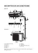
Connection of Indoor and Outdoor Cables
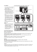
1. Pull open the front panel;
2. Unscrew the screw fastening the covering plate on
terminal board. (See Fig. 1);
3. Pass the power cable through a separate cable duct on
the back of indoor unit and pull it out from the front;
4. Connect the blue wire on the power connection
cables to the "N(1)" terminal of the terminal board,
connect the black wire to the "2" terminal, connect the
brown wire to the "3" terminal and connect the
yellow-green wire (grounding wire) to the "(
)"
terminal (See Fig. 2);
5. Place the section of power cable with protective pipe
into pressing groove and close the cover plate. Tighten
the fastening screws to clamp the connecting cable;
6. Install the front panel back in place;
Notes:
If the connecting cable is not long enough, please
contact the authorized service center for a length
of special cable. No joints are allowed in the cable.
• Make sure to connect the cable correctly.
Incorrect connection will cause malfunction of
some electrical parts.
• Tighten the terminal screw to prevent slack.
• After tightening the screw, gently pull the cable
taut.
• Incorrect connection of grounding cable may
cause electrocution.
• Make sure to fasten the junction cover plate
securely and press it tightly against the
connecting cable. Improper fastening may allow
dust or water to enter or expose connecting
terminal directly to external forces, and fire or
electrocution could occur.
Installing Indoor Unit
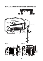
• Fitting pipe can come from four directions, i.e. right,
rear right, left and rear left.
1. When installing the pipe on the left or right side, trim
off any extra pipe left at the pipe outlet stub on the
base of the unit. (See Fig. 1).
• When drawing out the power line, cut extra part 1.
When drawing out the connecting pipe and the power
line, cut extra parts 1 & 2 (or 1, 2 & 3);
2. Pull the fitting pipe out of the bottom case. Use
adhesive tape to bind the fitting pipe, electrical cable
and drain hose properly and then pass them through
the fitting pipe hole (See Fig. 2).
3. Hang the claws on the back of the indoor unit to the hook on the wall-mounting frame. Move the unit
left and right to control that it is steady. (See Fig. 3).
4. The installation height of the indoor unit must be at least 2.3m.
40
Fig. 1
Fig. 2
Fig. 3
Extra Part 3
Extra Part 2
Extra Part 1
Fitting pipe on air side
Electrical cable for
external connection
Fitting
pipe on
liquid side
Heat insulation of
fitting pipe on air side
Finally, wrap with
adhesive tape.
Drainage Pipe
Left
Right rear
Left rear
Fastening
Hook
Mounting
Plate
Mounting
Plate
Right
Heat
insulation of
fitting pipe
on liquid side
Fig. 1
Fig. 2
Power
Connection
Cable
Blue
Brown
Black
Power Connection Cable
Yellow-Green
Covering plate
Connector

