27
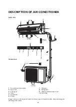
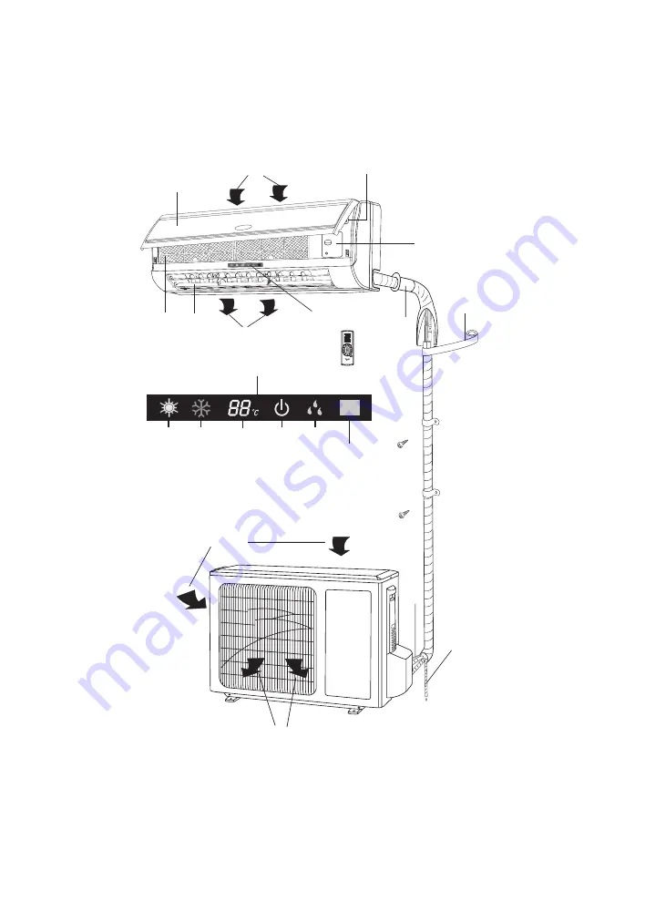
DESCRIPTION OF AIR CONDITIONER
1.
Terminal board cover plate
2.
Key switch
3.
Front panel
4.
Filter
5.
Guide louver
6.
Display
7.
Wall pipe
8.
Sealing tape
9.
Indoor & outdoor power cord
10.
Drain Pipe
(10)
(9)
(5)
(6)
(7)
(8)
(2)
(1)
(4)
(3)
(6)
Air inlet
Air outlet
Remote
Control
Indoor Unit
Outdoor Unit
Heat
Cool
Te
mperature
On
Dehumidify
Signal receiver
Air inlet
Air outlet
Images in the user instructions are based on external views of standard models, shape and design vary
according to the model.


