background image

4

BEFORE USING THE APPLIANCE

To make the most out of your new appliance,
please read the user instructions carefully and keep
them handy for future consultation.

Before using the appliance please follow and
set according to the below indications:
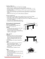
Remote Control (RC) presetting:

Each time the batteries are replaced in the remote
control, the RC is pre-set on Heat pump.  
If the air conditioner that you purchased is a
cooling only, then the pre-set on Heat pump will
not bring any changes.

Auto-Restart presetting Function:

To set the auto-restart function, press the
Emergency button (ON/OFF) on the indoor unit
for at least  5 seconds
A buzz sound will signal that the auto-restart
function is set and the air conditioner is in standby.
To cancel the auto-restart function, repeat the
above steps.

SAFETY PRECAUTIONS

• Do not install the appliance if it is connected to

the power supply.

• The Installation and service/repair must be

performed by a qualified technician, in
compliance with the producer's instructions and
following local safety norms. Do not repair or
replace any parts of the appliance unless it is
specifically written in the user instructions.

• The grounding of this appliance is compulsory.
• Make sure that the power supply cord is long

enough to allow the right connection. Do not
use any extension cord for power supply.

• Do not pull the power supply cord to remove it

from the socket.

• Do not twist or press the power supply cord,

and make sure it is not broken.

• Once installation is completed, the electric

components must not be accessible to the users.

• Do not touch the operation buttons when your

hands are wet and don't use the appliance when
you are barefoot.

• Physically or mentally disabled people, children

and people without any experience with the
product are only allowed to use the appliance if
they have had specific training on how to
operate the appliance by a person responsible
for their security and well-being. The appliance
is not intended for use by disabled people and
very young children without supervision.

Downloaded from AC-Manual.com Manuals

Summary of Contents for AMD 302

Page 1: ...a qualified technician in compliance with the producer s instructions and following local safety norms Do not repair or replace any parts of the appliance unless it is specifically written in the user instructions The grounding of this appliance is compulsory Make sure that the power supply cord is long enough to allow the right connection Do not use any extension cord for power supply Do not pull...

Page 2: ... cut off the mains cord so that the appliance cannot be re used For more detailed information on handling and recycling of this product contact your local authorities who deal with the separate collection of rubbish or the shop where you bought the appliance SCRAPPING OF PACKAGING The packaging can be 100 recycled as confirmed by the recycling symbol The various parts of the packaging must not be ...

Page 3: ...erature COOL MODE indicator lamp HEAT MODE indicator lamp Sleep indicator It lights up during sleep mode Timer indicator lamp If the batteries in the remote control are flat or the remote control is faulty use the Emergency operation switch 3 Emergency Operation switch The places of e different models maybe different but all of the emergency operation switch of emergency operation switches are sho...

Page 4: ...mer operation H 6TH SENSE button Used to enter fuzzy logic smart operation I TEMPERATURE ADJUSTMENT buttons Used to set time in TIMER on off mode and REAL TIME CLOCK Every press of the button increases the setting temperature by 1 C And the highest setting temperature is 31 C Every press of the button decreases the setting temperature by 1 C And the lowest setting temperature is 16 C J TIMER ON bu...

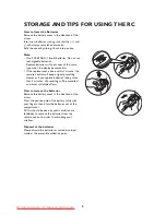
Page 5: ...te control will keep original presetting However if you replace batteries taking more than 3 minutes all presetting will be cancelled and timer will display Zero How to remove the batteries Remove the battery cover in the direction of the arrow Press the positive pole of the battery softly with your fingers then draw the batteries out of the compartment All this should be done by adults children a...

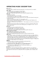
Page 6: ... Low Med High of the indoor unit HEAT mode heat pump type Press SWING button to change up down air flow direction Press FAN button to change the fan speed of the indoor unit Press ROOM TEMPERATURE ADJUSTMENT button to change the temperature setting SLEEP mode When this button is pressed the fan speed is low In sleep mode the temperature setting increases in cooling mode by 1 C or decreases in heat...

Page 7: ...R ON AND OFF When the unit and the remote controller are on press the timer off button to switch the remote controller and air conditioner to timer off mode Timer off is shown on the LCD display Time can be set from 1H to 24H with one hour increments each time the button is pressed Next press the timer on button to switch the remote controller and air conditioner to timer on mode Timer on is shown...

Page 8: ...utral detergent and then wipe it again with dry cloth Be sure not to use benzene solvent or other chemical products In the event of prolonged disuse 1 Switch the fan on for a few hours to dry out the inside thoroughly Choose COOL mode or HEAT mode and select the highest temperature setting then switch the fan on 2 Switch the air conditioner off Clean the filters and the outside of the unit 3 Remov...

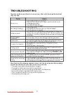
Page 9: ...city discharge power supply voltage abnormality Note that operation will be abnormal in this case unplug from the power supply and re plug after 2 3 seconds Does not operate immediately 3 minute delay will occur when changing mode during operation Peculiar smell This smell may come from another source such as furniture cigarette etc which is sucked in the unit and blown out with the air A sound of...

Page 10: ...e can be installed to the back right underside or left back side Notice do not raise the drain hose While installing the pipeline on thin armor plate or wire mesh wall use a wooden board to clamp between the wall and the pipeline or wrap the pipeline with 7 8 layers of insulating plastic tape Cover the connecting pipe with adiabatic material NOTICE D INSTALLATION above 105mm back right back unders...

Page 11: ...of wall post etc NOTICE The holes at solid arrow position must be secured to avoid the shake of mounting plate When the expansion bolts are used two holes 11 20 or 11 26 that the distance between them is 450mm should be adopted Drill on the wall Operation 1 Confirm the position of the wall hole according to the chart If it need to orientat a hole on the left side of the mounting plate please refer...

Page 12: ... Adiabatic pads must be used where the pipe passes through the wall ROUTE OF PIPE If the pipe comes out on the right side of the indoor unit cut part 1 of the unit If pipe comes out on the lower right side of the indoor unit cut part 2 of the unit If pipe comes out on the left side of the indoor unit cut part 3 of the unit REPOSITIONING THE DRAIN HOSE If the pipe comes out on the left side of the ...

Page 13: ...g the expansion orifice Arrangement of the drain hose To drain the condensation water easily the drain hose should be angled downwards The following 5 arrangement methods are incorrect If you find the drain hose is not long enough to connect to the indoor unit you can extend it with the hoses in the accessory box The section of the drain hose that passes through the wall must be lagged with specia...

Page 14: ...ed firmly The cable wire can be led from the back hole of the piping hole or ejecting hole Please utilize outdoor pipe support when the cable wire is led from the backside 4 Tighten the self tapping screw on the fixing clip 5 Install the maintenance board After the pipes and cable wire are installed please seal the sponge block as per drawing indication Outdoor unit terminal Connecting cable Maint...

Page 15: ...ue Brown Yellow Green Gray Black Brown Blue Outdoor unit terminal Plug housing 1 Plug housing 2 1 1 1 1 5 5 1 1 1 1 Cool only type Indoor unit terminal Connecting cable Yellow Green Outdoor unit terminal Brown Blue Blue Brown Black Heat pump type Heat pump type Heat pump type or or Plug housing 1 Brown Blue Yellow Green Plug housing 2 Gray Connecting cable Plug housing 1 Indoor unit terminal Plug ...

Page 16: ...rmation or contact the utility company Installation of the drain joint only for heat pump type Insert the outdoor double channel drain joint in one of the bottom holes of the right size then connect the drain hose and joint together Connecting pipe joint Use some airproof oil to cover the joint and the expanding orifice of the connecting pipe Align the centre of the joint with that of the expandin...

Page 17: ... the pipe orifice Use a pipe cutter to cut off the broken pipe orifice Remove burrs at the cut of the pipe orifice Insert a nut into the pipe and expand the orifice with specified tools reamers for example Check the quality of expanding technique Adding refrigerant If the connecting pipe is longer than 7 metres add refrigerant as needed Cool only type added amount A Lm 7m x 15g m Heat pump type ad...

Page 18: ...h is pressed the air conditioner runs in the following order Cool only type Cool Shut off Heat pump type Cool Heat Shut off 2 Remote control operation If the indoor unit beeps when the I O button is pressed this indicates the air conditioner is being operated with the remote control After that press every button to test operation 3 Check switch operation open the front grille and press the check b...

Reviews: