19
WARNING:
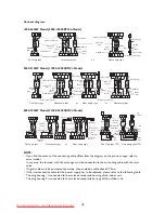
• The electric circuit diagram given on the indoor/outdoor units must be taken as the main reference for
installation.
• The power wires and signal wires between the indoor/outdoor units must be connected one by one as
per corresponding number on the wiring terminal board.
• The connecting cables must be clipped together.
• Special cable must be used to connect indoor unit and outdoor unit. It should be ensured that the
terminals are not influenced by external force. Poor connection may cause fire.
• The electric box cover must be mounted and secured in position, otherwise fire or electrical shock may
occur because of dust or moisture.
• All models must be connected to mains power with system impedance limitations.
• While installing the unit, please see the following table for impedance information or contact the utility
company.
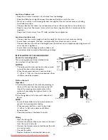
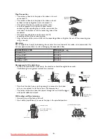
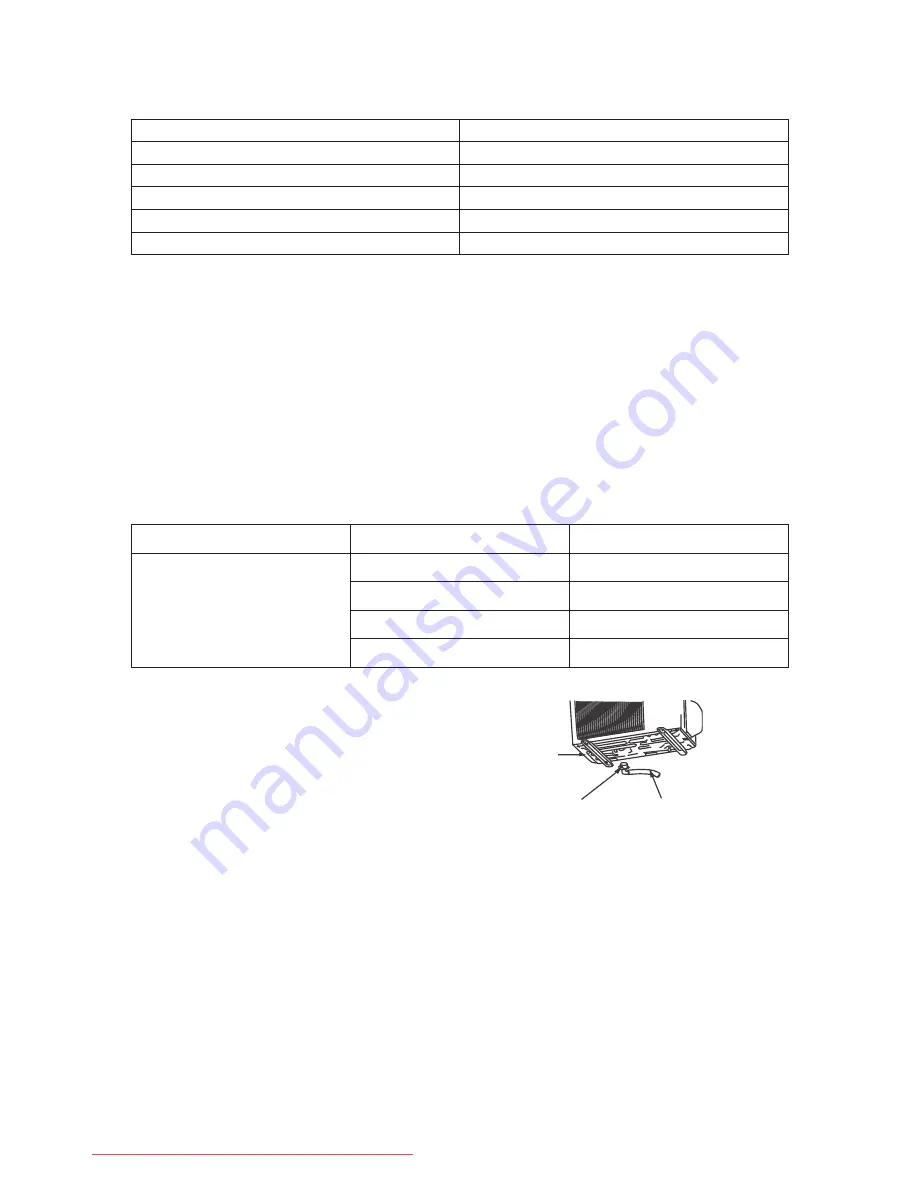
Installation of the drain joint (only for heat pump
type)
• Insert the outdoor double-channel drain joint in one of
the bottom holes of the right size then connect the drain
hose and joint together.
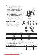
Connecting pipe joint
• Use some airproof oil to cover the joint and the expanding orifice of the connecting pipe.
• Align the centre of the joint with that of the expanding orifice and tighten the nut of the connecting pipe
with a wrench. (Adjust the torque using the same method used for connecting the pipe for the indoor
unit.)
MODEL
SPECS (Interconnection cable)
≤
2700W(10000BTU/h)
≥
1.0mm²
3200W(11000BTU/h) - 4000W(15000BTU/h)
≥
1.5mm²
4500W(16000BTU/h) - 8000W(28000BTU/h)
≥
2.5mm²
8500W(29000BTU/h) - 9500W(32000BTU/h)
≥
4.0mm²
10000W(34000BTU/h) - 11000W(38000BTU/h)
≥
6.0mm²
SERIES
MODEL
IMPEDANCE
R410A series
6800W (24000BTU/h)
≤
0.124
Ω
5100W (18000BTU/h)
≤
0.268
Ω
3500W (12000BTU/h)
≤
0.313
Ω
2500W (9000BTU/h)
≤
0.409
Ω
Bottom
Double-channel
drain joint
Drain hose
Downloaded from AC-Manual.com Manuals


