background image

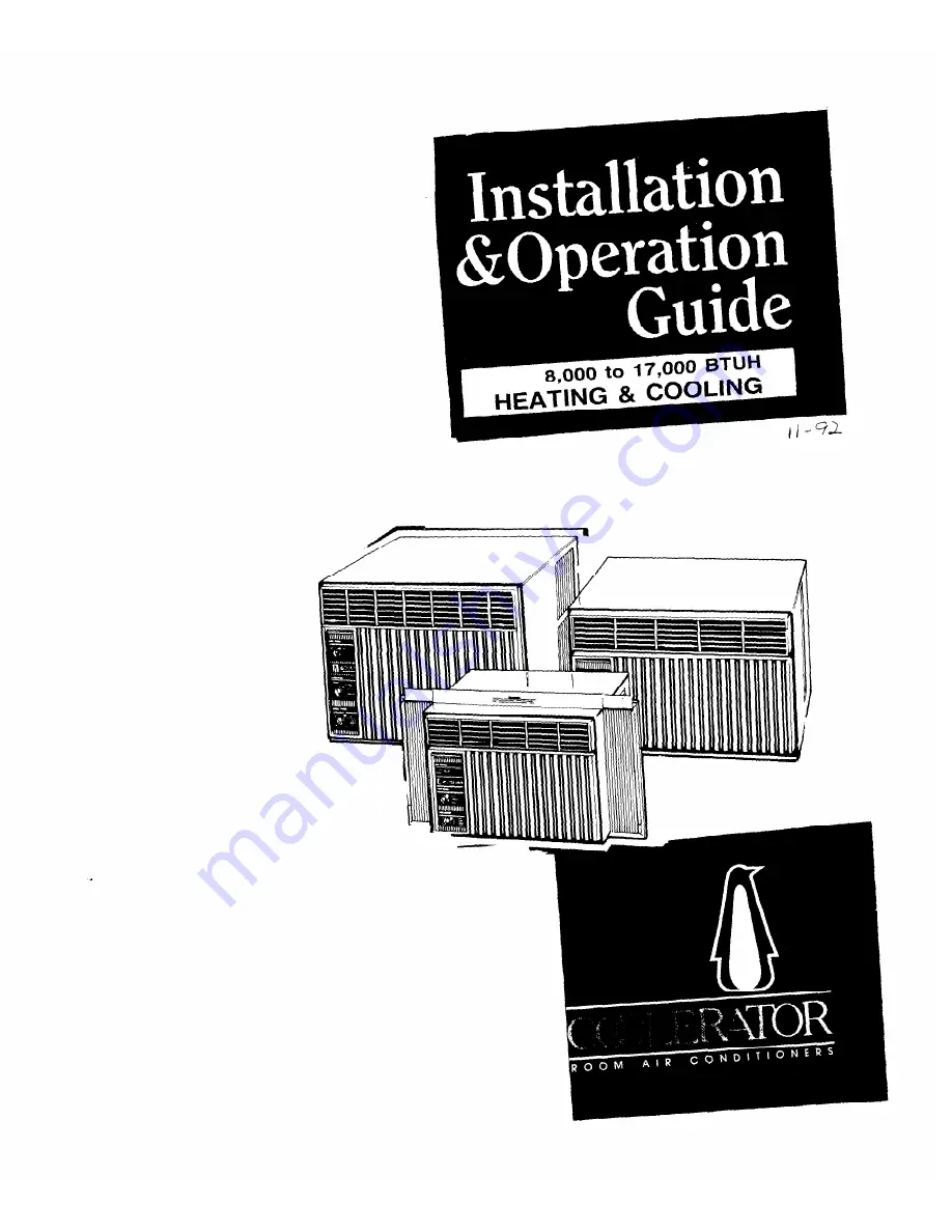
Summary of Contents for Coolerator Series

Page 1: ......

Page 2: ...buy guide Use damp cloth to take off any glue residue Do not use a sharp instrument or any harsh or abrasive cleaners Energy SavingTips l Improve home insulation seal doors windows and close fireplace flue l Close blinds or drapes on sunny side of house add window awnings l Keep air filter clean Don t block air flow with drapes or furniture l Ventilate attic high temperature levels add to normal c...

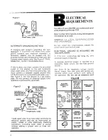
Page 3: ... as 14 cauge Use copper wire only It is the personai responsibility and obligation of the customer to provide proper and adequate receptacle wiring installed by a qualified electri cian OBSERVE NATIONAL ELECTRICAL CODE AND ALL LOCAL GOVERNING CODES AND ORDINANCES Electrical Requirements A 115 volt 103 5 min 126 5 max 60 hertz AC only 15 ampere fused electrical supply is required time delay fuse or...

Page 4: ... ground and not be interrupted by plastic rubber or other electrically insulating connectors including water meter or pump without adding a jumper wire at these con nections B ELECTRICAL REQUIREMENTS For 230 volt and 230 208 volt models with serial plate amperes up through 12 0 Refer to Chart B for specific wiring and receptacle information to be used OBSERVE ALL LOCAL GOVERNING CODES AND ORDINANC...

Page 5: ...IAL PLATE OF 2301206 For 230 volt and 230 208 volt models with serial plate amperes up through 16 0 Refer to Chart C for specific wiring and recep tacle information to be used OBSERVE ALL LOCAL GOVERNING CODES AND ORDINANCES Do not under any circumstances remove the power supply cord ground plug ELECTRICAL GROUND IS REQUIRED ON THIS APPLIANCE A three wire single phase 60 hertz AC only electrical s...

Page 6: ...ING CODES AND ORDINANCES Do not under any circumstances remove the power supply cord ground plug ELECTRICAL GROUND IS REQUIRED ON THIS APPLIANCE A three wire single phase 60 hertz AC only electrical supply is required A separate electrical supply is required on a separately fused circuit Do not fuse ground neutral See Chart D for receptacle voltage require ments proper fuse size wire and wiring co...

Page 7: ...N SPOUT USED ON MODELS WITH DRAIN CUP AND WEATHER HOLE IN SEAL USED REAR CABINET ON 18 3 4 RAIL HIGH CABINETS ONLY 0 SEAL STRIP Ya x X Some Models 2l Pick the right wall First decide what room s you want to cool Then choose a wall that will allow the air conditioned air to flow freely and directly into the room s you want cooled Remember it s difficult to move air around corners Choose a location ...

Page 8: ...de cabinet louvers A 4 minimum clearance between sidecabinet louvers and adjoining wall allows for proper airflow into air conditioner Figure 6 TNlS DIMENSION DEPENDS ON WALL TNICKNESS AND SED SE 26 DIMENSION CABINET 18 HIGH SE 17v2 DIMENSION FOR INCLUDES ALLOWANCE FOR 1 FLANGE ON BOl7OM OF I CABINET 5l Construct finish frame Apply creosote or something equal to the outside exposed surface 6 Insta...

Page 9: ...guide water Note the type of drain parts you have Insert drain cup according to instructions in Figure 8 Figure 8 1 PLACE PLASTIC DRAIN INTO HOLE IN REAR OF CABINET WITH SPOUT DOWN I r l L Q r l INTO METAL I BRACKET AND INSERT INTO I 1 CABINET RAIL SLOTS I TYPE 1 1 TYPE 2 Figure 9 I OUTSIDE 4 ROOM e SIDE 13l If you received one adhesive backed seal strip l 4 x l 2 remove paper backing from seal an...

Page 10: ...oose a fan speed setting for cooling or heating LO COOL for sleeping comfort HI COOL for maximum cooling LO HEAT for reduced air movement with heat HI HEAT for maximum air movement with heat 30Turn thermostat control to Number 6 mid setting You can adjust the air conditioner s per formance by resetting the thermostat control to a higher number for maximum cooling Lower the number setting for less ...

Page 11: ... to FAN ONLY FRESH AIR I FAN ONLY ChangingAir Direction The louvers in the grille area at the top of the air conditioner control the direction of the cooled air 1l Move the tabs at the bottom of the grille to the right left or straight ahead Simply move the tabs in the direction you want the air to go see Figure 13 2 On most models the louvers can only be adjusted left or right The front set is fi...

Page 12: ...ay from the bottom spring clips Figure 14 4 Clean front panel with warm water and mild soap or detergent Use a soft cloth Rinse and dry Replace front panel 5l Wipe control panel clean with a soft dry cloth CleaningAir Conditioner Filter The filter is cleanable A clean filter helps remove dust lint and other particles from the air Check every two weeks to see if filter needs cleaning 1l Remove filt...

Page 13: ...maintenance yourself If you decide to go ahead follow these steps 1 Oil the fan motor per instructions on the motor To add oil pull out the oil hole plug at each end of the motor See Figure 16 1l REMOVE UNIT FROM CABINET Wrap the motor electrical control box and electrical terminals box in plastic film and make sure no water or other liquid gets inside any of these parts It could damage the insula...

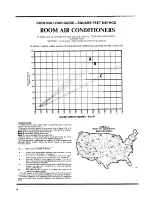
Page 14: ...rly exposure 4 From thus point read down to bonom of chart to determine required Btu hr output Write the Btulhr figure in the space indicated below 5 Btulhr from number 4 above 6 Locate your geographrc area on Inset map and multlply factor shown by figure rn number 5 _ If room air conditioner IS intended prlmarlly for nrghl time coohng subtract 30 from figure In number 6 6 p Subtract 30 Btuihr fro...

Page 15: ...s such as l Droplets of water hitting the condenser causing a pinging or clicking sound Water droplets help to cool the condenser 4 If you havea problem l Air movement from the fan especially on high fan speed setting Call our COOL LINE service assistance telephone number see Step 2 and talk with one of our Con sultants or if you prefer write to l Clicks from thermostat cycle 2 Sounds also may be ...

Page 16: ......

Reviews: