background image

INSTALLATION INSTRUCTIONS

27" (68.6 CM) AND 30" (76.2 CM) ELECTRIC BUILT-IN 

MICROWAVE/OVEN COMBINATION 

INSTRUCTIONS D'INSTALLATION DE L'ENSEMBLE FOUR À 

MICRO-ONDES ET FOUR CONVENTIONNEL 

ÉLECTRIQUES ENCASTRÉS DE 27" (68,6 CM) ET 

30" (76,2 CM)

BUILT-IN MICROWAVE/OVEN COMBINATION SAFETY

Table of Contents/Table des matières

BUILT-IN MICROWAVE/OVEN COMBINATION SAFETY......................1

INSTALLATION REQUIREMENTS ...........................................................2

Tools and Parts.......................................................................................2
Built-In Microwave/Oven Combination Location Requirements ...........2
Electrical Requirements ..........................................................................3

INSTALLATION INSTRUCTIONS .............................................................4

Prepare Built-In Microwave/Oven Combination ....................................4
Remove Oven Door ................................................................................4
Remove Oven Trim .................................................................................4
Make Electrical Connection....................................................................4
Install Oven .............................................................................................5
Complete Installation ..............................................................................6

SÉCURITÉ DE L'ENSEMBLE FOUR À 
MICRO-ONDES ET FOUR CONVENTIONNEL ENCASTRÉS ................ 7

EXIGENCES D'INSTALLATION................................................................ 7

Outillage et pièces .................................................................................. 7
Exigences d'emplacement de l'ensemble four à
micro-ondes et four conventionnel encastrés ....................................... 7
Spécifications électriques....................................................................... 8

INSTRUCTIONS D'INSTALLATION ......................................................... 9

Préparation de l'ensemble four à micro-ondes et 
four conventionnel encastrés ................................................................. 9
Dépose de la porte du four..................................................................... 9
Dépose de la garniture du four............................................................... 9
Raccordement électrique ..................................................................... 10
Installation du four ................................................................................ 11
Achever l'installation............................................................................. 12

You can be killed or seriously injured if you don't immediately 
 

You


can be killed or seriously injured if you don't follow 

All safety messages will tell you what the potential hazard is, tell you how to reduce the chance of injury, and tell you what can
happen if the instructions are not followed.

Your safety and the safety of others are very important.

We have provided many important safety messages in this manual and on your appliance. Always read and obey all safety 
messages.

This is the safety alert symbol.

This symbol alerts you to potential hazards that can kill or hurt you and others.

All safety messages will follow the safety alert symbol and either the word “DANGER” or “WARNING.”

These words mean:

follow instructions.

instructions.

DANGER

WARNING

IMPORTANT:


Save for local electrical inspector's use.

IMPORTANT :

À conserver pour consultation par l'inspecteur local des installations électriques.

W10192051A

Summary of Contents for Electric Built-In Microwave/Oven

Page 1: ...LLATION 9 Préparation de l ensemble four à micro ondes et four conventionnel encastrés 9 Dépose de la porte du four 9 Dépose de la garniture du four 9 Raccordement électrique 10 Installation du four 11 Achever l installation 12 You can be killed or seriously injured if you don t immediately You can be killed or seriously injured if you don t follow All safety messages will tell you what the potent...

Page 2: ... electrical supply is required See Electrical Requirements section Electrical supply junction box should be located 3 7 6 cm maximum below the support surface when the oven is installed in a wall cabinet A 1 2 5 cm minimum diameter hole should have been drilled in the right rear or left rear corner of the support surface to pass the appliance cable through to the junction box Oven support surface ...

Page 3: ...al number rating plate is located at the bottom of the right hand mounting rail See the following illustration Models rated from 7 3 to 9 6 kW at 240 volts 5 5 to 7 2 kW at 208 volts require a separate 40 amp circuit Models rated at 7 2 kW and below at 240 volts 5 4 kW and below at 208 volts require a separate 30 amp circuit A circuit breaker is recommended Connect directly to the circuit breaker ...

Page 4: ...Locate the oven door latches in both corners of the oven door and rotate the latches forward to the unlocked position 3 Grasp the edges of the oven door with both hands and close the oven door until it will no longer close Lift and pull oven door toward you and remove Set the oven door s aside on a covered work surface Remove Oven Trim 1 Side trims are located on the right side of the oven Cut the...

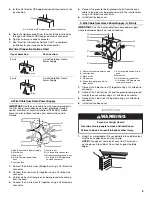
Page 5: ...om home power supply where local codes permit a 3 wire connection 1 Connect the 2 black wires C together using a UL listed wire connector 2 Connect the 2 white wires D and the green or bare ground wire of the oven cable using a UL listed wire connector 3 Connect the 2 red wires G together using a UL listed wire connector 4 Install junction box cover Install Oven 1 Using 2 or more people lift oven ...

Page 6: ...reference the Assistance or Service section of the Use and Care Guide or contact the dealer from whom you purchased your oven Complete Installation 1 Check that all parts are now installed If there is an extra part go back through the steps to see which step was skipped 2 Check that you have all of your tools 3 Dispose of recycle all packaging materials 4 For oven use and cleaning read the Use and...

Page 7: ...ur de la partie encastrée du four Une source d électricité avec liaison à la terre est nécessaire Voir la section Spécifications électriques Le boîtier de raccordement doit être situé au maximum à 3 7 6 cm au dessous de la surface de support lorsque le four est installé dans un placard mural Un trou de diamètre 1 2 5 cm ou plus doit avoir été percé dans l angle arrière gauche ou droit de la surfac...

Page 8: ...ource d électricité appropriée caractéristiques de tension et fréquence spécifiées sur la plaque signalétique La plaque signalétique est située en bas de la glissière de droite Voir l illustration ci dessous Modèles de 27 68 6 cm A Largeur de l encastrement 25 64 3 cm B Hauteur hors tout 42 107 6 cm C Largeur hors tout 26 67 9 cm D Profondeur de l encastrement 23 58 4 cm max E Hauteur de l encastr...

Page 9: ...rs de l installation 2 Pour éviter d endommager le plancher placer le four sur une feuille de carton avant l installation Lors des opérations de levage ne pas prendre prise sur la poignée ou sur une autre partie du châssis avant 3 Enlever les matériaux d emballage et les rubans adhésifs du four 4 Enlever le matériel à l intérieur du sachet de documentation 5 Enlever et conserver à part les grilles...

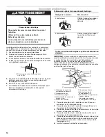
Page 10: ...structions et au Canada 1 Connecter ensemble les 2 conducteurs noirs B avec un connecteur de fils homologation UL 2 Connecter ensemble les 2 conducteurs rouges C avec un connecteur de fils homologation UL 3 Détorsader le conducteur blanc du conducteur vert ou nu de liaison à la terre provenant du four 4 Connecter ensemble les 2 conducteurs blancs F avec un connecteur de fils homologation UL 5 Conn...

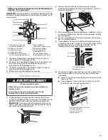
Page 11: ...is Phillips pour ôter les vis fixant les pieds installés pour l expédition 4 Pousser complètement le four dans le placard centrer le four dans la cavité du placard 5 Fixer solidement le four sur les éléments du placard avec les vis fournies n 8 14 de 1 2 pour un four simple 4 pour un four double Insérer les vis à travers les trous des rails de montage Ne pas serrer excessivement les vis 6 Sur cert...

Page 12: ...lage 4 Pour l utilisation et le nettoyage du four lire le Guide d utilisation et d entretien Vérification du fonctionnement du four inférieur 1 Mettre l appareil sous tension L affichage devrait indiquer PF 2 Appuyer sur BROIL cuisson au gril BROIL apparaît sur l affichage 3 Appuyer sur START mise en marche S assurer que la porte du four est fermée et que le témoin lumineux ON marche est allumé su...

Reviews: