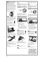
15.
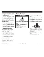
Push in and turn each surface unit
control knob to “LIGHT” position. The flame
should light within 4 seconds. Turn control
knob to “HIGH” position after burner lights.
Check each cooktop burner for proper flame.
The small inner cone should have a very
distinct blue flame 1/4" to 1/2"
long. The outer cone is not as
distinct as the inner cone.
Note: The cooktop burners have
been set at the factory for proper
operation. No adjustment is
required. If the burner does not
have the proper flame, call your dealer.
Electronic ignition system
Cooktop and oven burners use electronic
ignitors in place of standing pilots. When a
cooktop control knob is turned to the “LIGHT”
position, the system creates a spark to light
the burner. This sparking continues until the
control knob is turned to the desired setting.
When the oven control is set to the desired
setting, a series of sparks lights the oven
burner. The sparking will stop when burner
gas lights. Sparking will again occur to re-light
the burner everytime the burner cycles back
on again.
Check operation of cooktop
Page 6
Check operation
E
O
FF
LIG
H
T
H
G
IH
CLEAN
200
300
400
450
BROIL
PUSH TO
TURN
OFF
PUSH TO
TURN
WARM
250
350
500
OVEN ON
(TURN OFF OVEN WHEN FLASHING)
OVEN HEATING
DOOR LOCKED/CLEANING
(CLOSE DOOR WHEN FLASHING)
CLEAN
200
300
400
450
BROIL
PUSH TO
TURN
OFF
PUSH TO
TURN
WARM
250
350
500
OVEN ON
(TURN OFF OVEN WHEN FLASHING)
OVEN HEATING
DOOR LOCKED/CLEANING
(CLOSE DOOR WHEN FLASHING)
Push in and turn the oven selector control knob
to “350”. If the burner fails to light due to air
remaining in the gas line, reset the oven control
by turning selector knob to “OFF” and then
again to “350”.
Push in and turn the oven selector control knob
to “BROIL.” If the burner fails to light due to air
remaining in the gas line, reset the oven control
by turning selector knob to “OFF” and then
again to “BROIL”.
If your oven has electronic control pads only:
1. Press the “BAKE” pad.
• The “BAKE” indicator will light.
• “350” will appear in the display.
2. Press the START/ENTER pad.
• The “HEAT,” and “ON” indicators will
appear.
•
If the burner fails to light due to air remaining
in the gas line, reset the oven control by
pressing the “OFF/CANCEL” pad and then
pressing the “BAKE” and “START/ENTER”
pads again to reactivate the bake operation.
18.
Check the oven burner
for proper flame.
The flame should
be 1/2" long, with inner cone of
bluish-green, and outer mantle of
dark blue, and should be clean and
soft in character. No yellow tips,
blowing or lifting of flame should occur.
If
burner does not light, check that the regulator
shutoff valve is in the “on” position
(see Step 11).
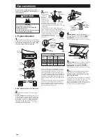
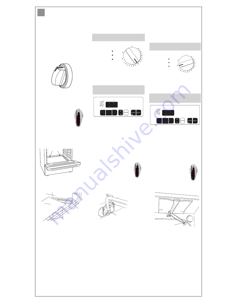
If oven flame needs adjusting:
Locate the air shutter next to the pressure
regulator. Loosen screw and adjust the air
shutter until the proper flame appears. Tighten
screw.
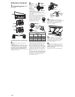
You can check the burner flame by removing the
flame spreader or by using a mirror.
Remove flame spreader:
Remove two screws from the front tabs of the
flame spreader. Lift front of the flame spreader
and pull forward to remove tabs from rear of
oven.
Using a mirror:
Insert mirror to one side of the burner. Look into
mirror to check flame.
stainless
steel/glass
mirror
flame
reflection
2 screws
If your range has an oven temperature
control knob:
If your range has an oven temperature
control knob:
flame
spreader
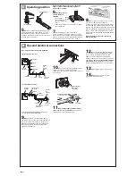
Remove oven bottom:
Remove two screws at the rear of the oven
bottom. Lift the rear of the oven bottom up and
back until the front of the panel is away from
the front frame. Remove from oven.
screws
Check operation of oven burner
16.
Open oven door.
19.
Turn the control knob to “OFF” or
press the “OFF/CANCEL” pad.
Check operation of oven broil
burner
21.
Follow the instructions for your type
of oven controls.
Note: A faint ticking sound will be heard while
the burner lights. The burner should light
within 8 seconds.
20.
Replace flame spreader, oven bottom
and oven racks.
If your oven has this type of electronic
control:
1. Press the “CUSTOM BROIL” pad.
• “525” or “HI” will appear in the display.
• The “BROIL” indicator will light.
2. Press the “START/ENTER” pad.
• “HEAT” and “ON” indicators will light.
• If the burner fails to light due to air
remaining in the gas line, reset the oven
control by pressing the “OFF/CANCEL” pad
and then pressing the “CUSTOM BROIL”
and “START/ENTER” pads again to
reactivate the bake operation.
TEMP
CLEAN
ON
BAKE
BROIL
START ?
HEAT
DOOR LOCKED
TIMER
TEMP
AUTO
CLEAN
BAKE
CUSTOM
BROIL
8 8 8
TEMP/
TIME
OFF
CANCEL
START
ENTER
5 SEC
CLOCK
TIMER
If your oven has this type of electronic
control:
TEMP
CLEAN
ON
BAKE
BROIL
START ?
HEAT
DOOR LOCKED
TIMER
TEMP
AUTO
CLEAN
BAKE
CUSTOM
BROIL
8 8 8
TEMP/
TIME
OFF
CANCEL
START
ENTER
5 SEC
CLOCK
TIMER
air shutter
and screw
regulator
shutoff valve
17.
Follow the instructions for your type
of oven controls.
Note: A faint ticking sound will be heard while
the burner lights. The burner should light within
8 seconds.
22.
Check the broil burner for
proper flame.
The flame should be
1/2" long, with inner cone of bluish-
green, and outer mantle of dark blue,
and should be clean and soft in
character. No yellow tips, blowing
or lifting of flame should occur.
If flame needs to be adjusted:
Loosen the lock screw on the air shutter
located at the rear of the broil burner.
Adjust the air shutter as needed.
Tighten lock screw.
You have just finished installing
your new range. To get the most
efficient use from your range, read
your Use & Care Guide.
Keep Installation Instructions and
Guide close to range for easy
reference. The instructions will make
installing the range in another home
as easy as the first installation.
23.
Turn the oven control knob to “OFF”
or press the “OFF/CANCEL” pad.
air shutter
and lock screw


