background image

4

Electrical Requirements 

If codes permit and a separate ground wire is used, it is 
recommended that a qualified electrical installer determine that 
the ground path and wire gauge are in accordance with local 
codes.
Check with a qualified electrical installer if you are not sure the 
cooktop is properly grounded.

It is not recommended to have a fuse in the neutral or ground 
circuit.
Make sure that the electrical connection and wire size are 
adequate and in conformance with the National Electrical Code, 
ANSI/NFPA 70-latest edition or CSA Standards C22.1-94, 
Canadian Electrical Code, Part 1 and C22.2 No. O-M91-latest 
edition, and all local codes and ordinances.
A copy of the above code standards can be obtained from:
National Fire Protection Association
One Batterymarch Park
Quincy, MA 02269
CSA International
8501 East Pleasant Valley Road
Cleveland, OH 44131-5575

Before You Make the Electrical Connection:

To properly install your cooktop, you must determine the type of 
electrical connection you will be using and follow the instructions 
provided for it here.

A 4-wire or 3-wire, single phase, 240 volt, 60 Hz., AC only 
electrical supply is required on a separate, 50-amp circuit 
(36" [91.4 cm] models) or 40-amp circuit (30" [76.2 cm] 
models), fused on both sides of the line. 

The cooktop should be connected directly to the junction box 
through flexible, armored or nonmetallic sheathed, copper 
cable. The flexible, armored cable extending from the fuse box 
or circuit breaker box should be connected directly to the 
junction box.

Locate the junction box to allow as much slack as possible 
between the junction box and the cooktop so that the cooktop 
can be moved if servicing becomes necessary in the future.

Do not cut the conduit. The length of conduit provided is for 
serviceability of the cooktop.

A UL listed or CSA approved conduit connector must be 
provided at each end of the power supply cable (at the 
cooktop and at the junction box). A listed conduit connector is 
already provided at the cooktop.

If the house has aluminum wiring, follow the procedure below:

1. Connect a section of solid copper wire to the pigtail 

leads.

2. Connect the aluminum wiring to the added section of 

copper wire using special connectors and/or tools 
designed and UL listed for joining copper to aluminum.

Follow the electrical connector manufacturer's recommended 
procedure. Aluminum/copper connection must conform with 
local codes and industry accepted wiring practices.

INSTALLATION INSTRUCTIONS

Prepare Location

1. Decide on the final location for the cooktop.

NOTE: Countertop must be 1

³⁄₁₆

" (3.0 cm) to 2" (5.1 cm) thick.

2. If necessary, make cutout in countertop before installing 

cooktop. See “Location Requirements” section for more 
information.

3. Clean cutout of any remaining dust and debris.

Install Brackets

NOTE: Kit Part Number W10310006 is required for installing the 
cooktop into a solid surface or marble countertop. See the 
“Assistance or Service” section of the Use and Care Guide for 
information on ordering.

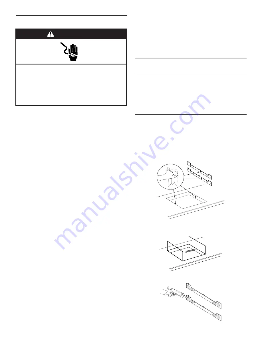
To Install Brackets into Marble Countertop:

1. Clean the brackets and cooktop cutout of any dust and 

debris.

2. Measure the center line of the vertical sides of the cooktop 

cutout.

3. Apply the adhesive provided in the kit to the back side of the 

brackets.

WARNING

Electrical Shock Hazard

Disconnect power before servicing.

Use 8 gauge copper wire.

Electrically ground cooktop.

Failure to follow these instructions can result in death, 
fire, or electrical shock.

Center line

Summary of Contents for GCI3061

Page 1: ...e cuisson 14 Raccordement électrique 14 Achever l installation 16 You can be killed or seriously injured if you don t immediately You can be killed or seriously injured if you don t follow All safety messages will tell you what the potential hazard is tell you how to reduce the chance of injury and tell you what can happen if the instructions are not followed Your safety and the safety of others a...

Page 2: ... plate The model serial rating plate is located on the underside of the cooktop burner box 30 76 2 cm cooktop model serial rating plate location models JIC4430 GCI3061 ICI500 KICU500 and KICU509 36 91 4 cm cooktop model serial rating plate location models JIC4536 and KICU569 Check the cooktop base for an approved installation label Verify approved oven model number that can be installed with your ...

Page 3: ... 1 cm B 30 78 2 cm C 2 6 0 cm Models JIC4536 and KICU569 A 21 54 1 cm B 36 92 0 cm C 2 6 0 cm C A B C A B A 29 75 0 cm on 30 76 2 cm models 33 84 0 cm on 36 91 4 cm models B Combustible area above countertop shown by dashed box above C 30 76 2 cm minimum clearance between top of cooktop platform and bottom of uncovered wood or metal cabinet 24 61 cm minimum clearance if bottom of wood or metal cab...

Page 4: ...o that the cooktop can be moved if servicing becomes necessary in the future Do not cut the conduit The length of conduit provided is for serviceability of the cooktop A UL listed or CSA approved conduit connector must be provided at each end of the power supply cable at the cooktop and at the junction box A listed conduit connector is already provided at the cooktop If the house has aluminum wiri...

Page 5: ...ine and align the upper edge of the brackets so that they are flush with the countertop 3 Attach the brackets in the cutout with the screws provided Install Cooktop 1 Using 2 or more people lower the cooktop into the cutout making sure the clips on each side of the cooktop line up with the brackets in the cutout 2 Push down on cooktop to snap the cooktop clips onto the brackets installed in the cu...

Page 6: ...en or bare ground wire C from the cooktop cable to the green or bare ground wire in the junction box using a UL listed wire connector 3 Put a UL listed wire connector on the end of the white wire F NOTE Do not connect the green or bare ground wire to the neutral white wire in the junction box 4 Connect the 2 black wires H together using a UL listed wire connector 5 Install junction box cover A UL ...

Page 7: ...sehold cleaner and warm water to clean cooktop before use Dry thoroughly with a soft cloth For more information see the Cooktop Care section of the Use and Care Guide 5 Read Cooktop Use in the cooktop Use and Care Guide 6 Reconnect power NOTE If the cooktop does not work after turning on the power check that a circuit breaker has not tripped or a household fuse has not blown See Troubleshooting se...

Page 8: ...8 Notes ...

Page 9: ...ble de décès ou de blessure grave si vous ne suivez pas les instructions Tous les messages de sécurité vous diront quel est le danger potentiel et vous disent comment réduire le risque de blessure et ce qui peut se produire en cas de non respect des instructions Votre sécurité et celle des autres est très importante Nous donnons de nombreux messages de sécurité importants dans ce manuel et sur vot...

Page 10: ...4536 et KICU569 Vérifier que la base de la table de cuisson comporte une étiquette d installation approuvée Vérifier le numéro de modèle de four approuvé pouvant être installé avec votre numéro de modèle de table de cuisson Si vous ne trouvez pas cette étiquette il se peut que votre table de cuisson ne soit pas approuvée pour une utilisation au dessus d un four encastré Les fours approuvés pour ce...

Page 11: ...76 2 cm 33 84 cm sur les modèles de 36 91 4 cm B Zone de matière combustible au dessus du plan de travail espace délimité par des lignes pointillées ci dessus C Distance minimale de séparation de 30 76 2 cm entre le dessus de la table de cuisson et le fond d un placard métallique ou de bois non couvert distance de séparation de 24 61 cm ou plus si le fond du placard de métal ou de bois est recouve...

Page 12: ...e cuivre avec blindage ou gaine non métallique Le câble blindé flexible sortant du boîtier de distribution fusible ou disjoncteur doit être raccordé directement au boîtier de connexion Repérer le boîtier de connexion pour laisser le plus d espace possible entre celui ci et la table de cuisson pour pouvoir déplacer la table de cuisson en cas de besoin de réparation à l avenir Ne pas couper le condu...

Page 13: ...dhésif fourni avec la trousse sur l arrière des supports 4 Positionner les supports au centre de l axe central vertical et aligner la rive supérieure des supports de façon à ce qu ils soient en affleurement avec le plan de travail 5 Enfoncer fermement les supports sur chaque côté de l ouverture de la table de cuisson et attendre 1 heure pour que l adhésif puisse sécher Installation des supports da...

Page 14: ...s échéant 5 Voir Tableau des options de raccordement électrique pour terminer l installation correspondant à votre type de raccordement électrique Tableau des options de raccordement électrique A Attache A Table de cuisson B Ouverture de la table de cuisson AVERTISSEMENT Risque du poids excessif Utiliser deux ou plus de personnes pour déplacer et installer la table de cuisson Le non respect de cet...

Page 15: ...ribution du domicile É U seulement IMPORTANT Utiliser le câble à 3 conducteurs depuis le point de distribution du domicile lorsque les codes locaux autorisent un tel raccordement 1 Connecter ensemble les 2 conducteurs rouges B avec un connecteur de fils homologation UL 2 Connecter le conducteur vert ou nu de la table de cuisson C au conducteur blanc neutre F dans le boîtier de connexion avec un co...

Page 16: ...entretien 5 Lire Utilisation de la table de cuisson dans le Guide d utilisation et d entretien de la table de cuisson 6 Reconnecter la source de courant électrique REMARQUE Si la table de cuisson ne fonctionne pas une fois que l appareil a été mis sous tension vérifier que le disjoncteur n est pas déclenché ou que les fusibles ne sont pas grillés Voir la section Dépannage dans le Guide d utilisati...

Reviews: