4-10
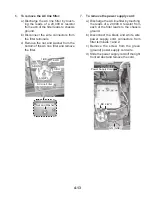
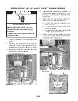
c) Depending on which component you
are servicing, disconnect the wire con-
nectors from the stirrer motor or cavity
thermostat #2 terminals, and remove
the component from the oven.
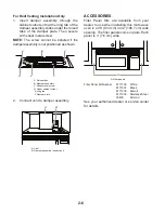
9. Lift the rear of the top subpanel assembly,
pull it back slightly, raise the front, and re-
move the wires from the three indicated
clips.
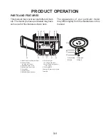
10. Prop the top assembly up so that you can
access the stirrer motor, cavity thermo-
stat #2, and cavity lamp holder.
3 Wire Clips
Stirrer Motor
Cavity Thermostat #2
Cavity Lamp Holder
12.
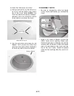
To remove the stirrer motor and cavity
thermostat #2:
a) Remove the two screws from the stir-
rer motor.
b) Lift the stirrer motor straight up so that
the fan pulls off the motor shaft, and
remove the motor.
Stirrer Motor
Screw (1 of 2)
Stirrer Motor Connectors
Cavity Thermostat #2 Connectors
11.
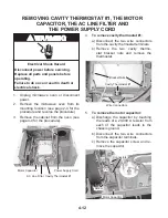
To remove the cavity lamp holder (see
the top-right photo):
a) Remove the Silastic
™
from the bulb
and the base of the lamp holder.
b) Remove the bulb from the lamp holder.
c) Disconnect the two wire connectors
from the lamp holder terminals.
d) Rotate the lamp holder clockwise to
release the base from the mounting
bracket and remove the cavity lamp
holder.
Remove Silastic
™
Connectors
Bulb
Lamp Holder Base
Screwdriver
as prop

