background image

5-8

TURNTABLE MOTOR

Refer to page 4-25 for the procedure for ac-

cessing the turntable motor.
1.  Unplug  microwave  oven  or  disconnect 

power.

2.  Disconnect  one  of  the  wires  from  the 

turntable motor terminals.

3.  Set the ohmmeter to the R x 10K scale.
4.  Touch  the  ohmmeter  test  leads  to  the 

motor terminals. The meter should indi-

cate between 2700 and 3800 

Ω.

HIGH-VOLTAGE TRANSFORMER

Refer to page 4-24 for the procedure for ac-

cessing the high-voltage (H.V.) transformer.
1.  Unplug  microwave  oven  or  disconnect 

power.

2.  Disconnect the wires from the  H.V. trans-

former terminals.

3.  Disconnect the  H.V. transformer wires from 

the magnetron and the H.V. capacitor.

4.  Set the ohmmeter to the R x 1 scale.
5.  Touch the ohmmeter test leads to the fol-

lowing H.V. transformer locations: 

Filament  wire  (org/red)  to  ground  =      

• 

Infinite.
Primary terminals (red & white) wires = 

• 

less than 1 Ω.
Secondary (red & white) wires = 60 Ω 

• 

(approximately).

     Primary    

  Terminals

   Filament    

 Wire (OR/RD)

 Secondary Wires   

 (WH and RD)

Electrical Shock Hazard

Disconnect power before servicing.
Replace all parts and panels before operating.
Failure to do so can result in death or electrical shock.

WARNING

Summary of Contents for GH4184XSB

Page 1: ...CONSUMER SERVICES TECHNICAL EDUCATION GROUP PRESENTS MICROWAVE OVEN HOOD COMBINATION JOB AID Part No 8178707 KM 31 Models MH3184XPB GH4184XSB GH4814XSS ...

Page 2: ...Repair Help DIY Videos Visit A ApplianceAssistant com Note This Page was not included by Whirlpool Corporation ApplianceAssistant com is not affiliated Whirlpool Corporation Whirlpool Corporation in no way endorses ApplianceAssistant com ...

Page 3: ... The Wiring Diagram and Strip Circuits used in this Job Aid are typical and should be used for training purposes only Always use the Wiring Diagram supplied with the product when servicing the unit GOALS AND OBJECTIVES The goal of this Job Aid is to provide information that will enable the In Home Service Profes sional to properly diagnose malfunctions and repair the KitchenAid Microwave Oven Hood...

Page 4: ... Removing Cavity Thermostat 3 and the Humidity Sensor 4 5 Removing the Hood Exhaust Fan Motor 4 8 Removing the Cavity Lamp Holder the Stirrer Motor and Cavity Thermostat 2 4 9 Removing Cavity Thermostat 1 the Motor Capacitor the AC Line Filter and the Power Supply Cord 4 12 Removing the Electronic Control Board and the Touch Control Assembly 4 14 Removing the Primary Secondary and Monitor Interloc...

Page 5: ...tage Diode 5 6 Power Resistor 5 6 High Voltage Capacitor 5 7 Magnetron 5 7 High Voltage Transformer 5 8 Turntable Motor 5 8 DIAGNOSTICS AND TROUBLESHOOTING 6 1 Primary Secondary and Monitor Interlock Switch Checkout Procedure 6 1 Failure Code Indications 6 2 Touch Panel and Electronic Control Test 6 3 Microwave Oven Power Output Test 6 4 WIRING DIAGRAM AND STRIP CIRCUITS 7 1 Wiring Diagram 7 1 Str...

Page 6: ... that can kill or hurt you and others All safety messages will follow the safety alert symbol and either the word DANGER or WARNING These words mean All safety messages will tell you what the potential hazard is tell you how to reduce the chance of injury and tell you what can happen if the instructions are not followed You can be killed or seriously injured if you don t immediately follow instruc...

Page 7: ...ping or Abuse c Before turning on microwave power for any service test or inspection within the microwave generating compartments check the magnetron waveguide or transmission line and cavity for proper alignment integrity and connections d Any defective or misadjusted components in the interlock monitor door seal and micro wave generation and transmission systems shall be repaired replaced or adj...

Page 8: ...9 CUBIC FEET 04 0 4 CU FT 13 1 3 CU FT 06 0 6 CU FT 14 1 4 CU FT 07 0 7 CU FT 15 1 5 CU FT 08 0 8 CU FT 16 1 6 CU FT 09 0 9 CU FT 17 1 7 CU FT 10 1 0 CU FT 18 1 8 CU FT 11 1 1 CU FT 19 1 9 CU FT 12 1 2 CU FT FEATURE LEVEL 0 30 KIT IF KIT 2 22 KIT IF KIT 4 24 KIT IF KIT 5 SENSORED MODEL 7 27 KIT IF KIT FEATURE CODE C CSA APPROVED N I enabled with In Home Warranty S CARRY IN WARRANTY effective 02 96...

Page 9: ...rial Number label and Tech Sheet locations are shown below Model Serial Number Label Tech Sheet Location Electrical Shock Hazard Disconnect power before servicing Replace all parts and panels before operating Failure to do so can result in death or electrical shock WARNING ...

Page 10: ... 1 2 X 4 3 4 Technical Error Indication F With Error Number Diagnostic System Yes Oven Interior Features Size Inches 22 7 8 w x 9 1 2 h x 14 1 2 d Size Metric 580 mm W x 236 mm H x 370 mm D Capacity 1 8 Cu Ft Finish Powder Coating Cooking Power 1000 Watts Glass Turntable Diameter 12 Ventilation Standard Air Flow System Cooling Fan Automatic On if Oven Is Operating Off If Door Is Open Door Features...

Page 11: ...res Cabinet Finish White Black Biscuit Black for Stainless Cooktop Light w Touch Control 2 Lamps 30 Watt Easy Access Power Cord Length 3 Feet Other Specifications Electrical 120 VAC Single Phase 60 Hz 1500 Watts For Use With 15 20 Amp Circuit Domestic Use Only Yes Agency Approvals FCC DHHS CDRH UL Approx Net Weight Lb 62 Lbs APPROVED ACCESSORIES Hardware for Installation Yes 1 Set Literature Use C...

Page 12: ...Technical Error Indication F With Error Number Diagnostic System Yes Oven Interior Features Size Inches 22 7 8 w x 9 1 2 h x 14 1 2 d Size Metric 580 mm W x 236 mm H x 370 mm D Capacity 1 8 Cu Ft Turn Table Yes Sunken Flush 12 dia Ventilation Standard Air Flow System Cooling Fan Automatic On if Oven Is Operating Off If Door Is Open Light Automatic Turns on when oven door is open or oven is oper at...

Page 13: ...ensions in 29 7 8 W x 17 1 4 H x 15 7 16 D Power Cord Length 3 Feet Other Specifications Electrical 120 VAC Single Phase 60 Hz 1500 Watts For Use With 15 20 Amp Circuit Domestic Use Only Yes Agency Approvals FCC DHHS CDRH UL Approx Net Weight Lb 55 Lbs APPROVED ACCESSORIES Tupperware Steam Cook Vessel No optional Exhaust Damper Assembly Yes 1 Set Hardware for Installation Yes 1 Set Literature Use ...

Page 14: ...TALLATION INFORMATION INSTALLATION REQUIREMENTS 30 76 2 cm is typical for 66 167 6 cm installation height Exact dimensions may vary depending on type of range cooktop below A 2 x 4 wall stud B Grounded 3 prong outlet 66 167 6 cm min 12 30 5 cm min 14 35 6 cm max A B 30 76 2 cm typical 30 76 2 cm min 297 8 75 9 cm 153 8 39 1 cm 171 8 43 5 cm 157 8 40 3 cm ...

Page 15: ... tions are not completely understood or if doubt exists as to whether the micro wave oven is properly grounded Do not use an extension cord If the power supply cord is too short have a qualified electrician or serviceman install an outlet near the microwave oven WARNING Electrical Shock Hazard Plug into a grounded 3 prong outlet Do not remove ground prong Do not use an adapter Do not use an extens...

Page 16: ...mper plate and screw together and set aside 3 Remove two screws attaching blower motor to back of microwave oven A Screws A 4 Lift blower motor out of microwave oven A Blower motor A 5 Rotate blower motor end over end 6 Rotate blower motor so that exhaust ports face the back of microwave oven and lower blower motor back into the microwave oven 7 Reattach blower motor to back of microwave oven with...

Page 17: ...en with 2 screws removed in Step 3 of Wall Venting Installation Only Securely tighten screws NOTE If blower motor is not correctly orient ed the 2 screws removed in Step 3 cannot be reattached to the microwave oven A Damper plate B Tabs at back of damper plate C Slots in back of microwave oven exterior D Damper plate tabs E Slots in top of microwave oven exterior A B C D E 7 Reattach damper plate ...

Page 18: ...eed to be adjusted skip steps 7 9 7 If adjustment is required rotate the microwave oven downward Using 2 or more people lift microwave oven off of mounting plate and set aside on a pro tected surface 8 Loosen mounting plate screws Adjust mounting plate and retighten screws 9 Repeat steps 3 6 10 With the microwave oven centered and with at least one person holding it in place insert bolts through u...

Page 19: ...Sheet metal screw D Upper cabinet cutout E Long tab F Damper plate A B C D E F 2 Connect vent to damper assembly A Vent B Damper assembly under vent A B ACCESSORIES Filler Panel Kits are available from your dealer to use when installing this microwave oven in a 36 91 4 cm or 42 106 7 cm wide opening The filler panels come in pairs Each panel is 3 7 6 cm wide A Filler panels A Filler Panel Kit Numb...

Page 20: ...behind Vent Grille C Microwave Inlet Cover D Microwave Oven Light E Vent Grille F Control Panel G Metal Shielded Window H Cooktop Light I Cooking Guide Label J Grease Filters shipped in oven cavity K Cooking Rack Parts and Features not shown Turntable B A C D I H J H E F K G A Turntable B Hub C Support D Shaft A B C D The appearance of your particular model may differ slightly from the illustratio...

Page 21: ...hed within 5 seconds after touching a pad START will appear on the display as a reminder If not touched within 5 minutes after touching a pad the display will return to the time of day mode and the pro grammed function will be canceled If cooking is interrupted touching the START will resume the preset cycle The ADD 30 SEC control starts the oven at 100 power for 30 seconds and adds 30 sec onds of...

Page 22: ...start or stop the microwave oven When the Timer is in use the microwave oven can also operate To see the countdown for 5 seconds when the microwave oven is in use touch TIMER SET OFF To Set 1 Touch Timer If no action is taken after 1 minute the dis play will return to the time of day mode 2 Touch the number pads to set the length of time 3 Touch Timer or START If Timer or START is not touched with...

Page 23: ...gh the four speeds and then turn the fan off COOKTOP LIGHT The cooktop light has three settings on night and off To Turn On Night Off Touch Light On Night Off pad repeatedly to cycle through the settings DEMO MODE The Demo Mode is ideal for learning how to use the microwave oven When set functions can be entered without actually turning on the magnetron Themicrowaveovenlightwillcome on the fan wil...

Page 24: ... Hood Exhaust Fan Motor Cavity Thermostat 2 Cavity Thermostat 1 AC Line Filter Fuse Holder Line Fuse Fuse 4 amp Cavity Lamp Lamp Holder Hood Cooktop Lamp Turntable Motor Primary Interlock Switch Monitor Interlock Switch Secondary Interlock Switch Touch Panel membrane switch Electronic Control Fuse 25 amp Exhaust Fan Thermostat Hood Cooktop Lamp Lamp Holder H V Diode H V Capacitor Cooling Fan Motor...

Page 25: ...Failure to do so can result in death or electrical shock WARNING 3 To remove a hood lamp socket a Remove the screw from the lamp socket mounting plate and remove the plate from the holder see the top right photos Bottom Cover Assembly Screw 1 of 10 b Pull the bulb from the lamp socket c Cut the lamp socket wires near the sock et and splice a new socket and mount ing plate in its place Lamp Holders...

Page 26: ...otor terminals b Unlatch and disconnect the 6 hole power connector from the microwave oven and unclip the wires from the standoff c Unhook the bottom cover assembly from the microwave oven and remove assembly Turntable Motor Connector Power Connector Wire Standoff Bottom Cover Assembly ...

Page 27: ...from the oven WARNING 5 Remove the five flat head screws from the top of the cabinet Front Air Vent 4 Remove the screw from the top vent cover Push the vent towards the back unhook it and remove the vent from the top of the cabinet Vent Cover Screw Unhook Top Vent Cover 5 Top Cabinet Screws 6 Remove the following screws from the cabinet a One right side screw b Eight rear screws c Six bottom side ...

Page 28: ...he cabinet from the oven see page 4 4 for the procedure WARNING Cavity Thermostat 3 and Humidity Sensor 4 To remove cavity thermostat 3 a Disconnect the wires from the thermo stat terminals see the top right photo b Press down on the two holder locking tabs rotate the thermostat counter clockwise until it is free of the catches and remove the thermostat 5 To remove the humidity sensor a Remove the...

Page 29: ...and move the holder to the left e Disconnect the 3 wire humidity sen sor cable red white and black from humidity sensor connector P1 d Remove the top screw from the control panel Open the oven door lift the pan el unhook the side latching tabs from the slots and tilt the panel forward f Remove the humidity sensor cable from the clips in the bottom of the top cover and along the right front air gui...

Page 30: ...sition the sensor cable facing down and the green ground wire at the indicated screw g Remove the two screws and the end of the green ground wire from the hu midity sensor h Pull the end of the humidity sensor cable from under the top cover Humidity Sensor Screws Green Ground Wire ...

Page 31: ...he microwave oven from its mounting location see page 2 4 for the procedure and do procedure in reverse 3 Remove the cabinet from the oven see page 4 4 for the procedure WARNING 4 Remove the two hood exhaust fan motor screws from the rear panel 5 Unlatch and disconnect the hood exhaust fan motor wire connector from the oven 6 Lift the hood exhaust fan motor out of the oven and remove it Hood Exhau...

Page 32: ... WARNING 4 Remove the hood exhaust fan motor see page 4 8 for the procedure 5 Remove the two top subpanel screws from the rear panel see the top right photo 6 Lift the right rear air guide and unhook it from the right front air guide 7 Pull the power supply cord off the right front air guide 8 Remove the five indicated screws from the top subpanel Remove the left air grille and the wire grille fro...

Page 33: ...To remove the stirrer motor and cavity thermostat 2 a Remove the two screws from the stir rer motor b Lift the stirrer motor straight up so that the fan pulls off the motor shaft and remove the motor Stirrer Motor Screw 1 of 2 Stirrer Motor Connectors Cavity Thermostat 2 Connectors 11 To remove the cavity lamp holder see the top right photo a Remove the Silastic from the bulb and the base of the l...

Page 34: ...e on the motor shaft before you reinstall the cover f Use the putty knife and scrape the old Silastic from around the stirrer fan opening Use a piece of fine sandpaper to clean any debris from the surface Remove Silastic Apply a 1 8 bead of Silastic around the stirrer motor cover opening Make sure that the bead goes completely around the opening with no breaks so that a complete seal is made betwe...

Page 35: ...ee page 4 4 for the procedure WARNING Motor Capacitor AC Line Filter Power Supply Cord Cavity Thermostat 1 4 To remove cavity thermostat 1 a Disconnect the two wire connectors from the cavity thermostat terminals b Remove the two cavity thermo stat bracket nuts and remove the thermostat Cavity Thermostat 1 Wire Connectors Bracket Nuts 5 To remove the motor capacitor a Discharge the capacitor by to...

Page 36: ...filter AC Line Filter 1 BK 2 WH 3 BU 4 GN YL 5 BRN Nut and Washer 7 To remove the power supply cord a Discharge the AC line filter by touching the leads of a 20 000 Ω resistor from each of the filter leads to the chassis ground b Disconnect the black and white wire power supply cord connectors from filter terminals 1 and 2 c Remove the screw from the green ground power supply cord wire d Slide the...

Page 37: ... top screw from the control panel Open the oven door lift the panel unhook the side latching tabs from the slots and tilt the panel forward 5 Disconnect the 3 wire humidity sen sor cable red white and black from humidity sensor connector P1 Humidity Sensor Connector P1 P2 Relay BN RD P4 P3 Green Ground Wire Screw 6 Lift the control panel and unhook the bot tom bracket from the slot in the chassis ...

Page 38: ...uch panel are replaced as one assembly 10 To remove the electronic control board a Lift the locking arm on ribbon cable connector P5 and pull the cable out of the connector b Remove the four screws from the elec tronic control board c Release the two locking tabs and re move the electronic control board from the panel Locking Tab 4 Screws Locking Arm Electronic Control Board Metal Shield Locking T...

Page 39: ...nd disconnect the gray NC2 and white C1 wires from the switch terminals Pins and Locking Tabs Monitor Interlock Switch White Wire C1 Gray Wire NC2 c While pulling out on the switch pry up on the locking tab so that it clears the switch d Repeat the previous step for the other pin and locking tab and slide the switch off the holder pins 3 To remove the monitor interlock switch a Open the microwave ...

Page 40: ...lock Switch Press down on the locking tabs and disconnect the orange NC2 brown and white NC4 and black C1 wires from the switch ter minals see the upper right photo Interlock Switch Assembly Screw g SecondaryInterlockSwitch Pressdown on the locking tabs and disconnect the blue and white NC2 and blue and black C1 wires from the switch terminals REASSEMBLY NOTE Be sure to rotate the switch cam back ...

Page 41: ...e procedure 4 To remove the magnetron thermostat a Disconnect the two wires from the mag netron thermostat terminals b Remove the screws from the magnetron thermostat and remove the thermostat 3 To remove the line fuse holder a Remove the line fuse from the fuse holder b Disconnect the two wire connectors from the fuse holder terminals Magnetron Thermostat c Remove the screw from the fuse holder a...

Page 42: ...cooling fan motor see step 3 b Disconnect the two wires from the ex haust fan thermostat terminals c Remove the screws from the ex haust fan thermostat and remove the thermostat 3 To remove the cooling fan motor a Remove the two right screws from the fan motor see the top right photo b Disconnect the two wires from the fan motor terminals c Pull the cooling fan motor to the right unhook the left s...

Page 43: ...voltage diode a Discharge the high voltage capacitor by touching the leads of a 20 000 Ω re sistor from each of the capacitor leads to the chassis ground b Disconnect the high voltage diode connector from the high voltage ca pacitor terminal c Remove the screw and washer from the high voltage diode and remove the diode from the high voltage capacitor High Voltage Diode Power Resistor 5 To remove t...

Page 44: ...ave oven from its mounting location see page 2 4 for the procedure and reverse the procedure 3 Remove the cabinet from the oven see page 4 4 for the procedure 4 Remove the cooling fan motor from the oven see page 4 19 for the procedure 5 Unclip the wiring from the front of the fan shroud 6 Remove the two top front and bottom screws 6 total from the fan shroud High Voltage Capacitor Magnetron Top F...

Page 45: ...from the power resistor terminals 10 Cut the wire tie from around the power resistor wires 11 Remove the power resistor wires and the high voltage transformer wires from the cooling fan shroud 12 Slide the cooling fan motor shroud out of the oven Power Resistor Wires Cut Wire Tie Cut Foam Tape On Shroud 3 Places High Voltage Transformer Wires Remove Cooling Fan Motor Shroud High Voltage Capacitor ...

Page 46: ...e the four screws from the mag netron and remove the magnetron from the oven 13 To remove the high voltage capaci tor a Discharge the high voltage capacitor by touching the leads of a 20 000 Ω re sistor from each of the capacitor leads to chassis ground b Remove the high voltage diode from the capacitor see page 4 20 for the procedure c Disconnect the wire connectors from the high voltage capacito...

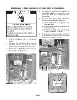
Page 47: ...ge 4 4 for the procedure High Voltage Transformer 4 Discharge the high voltage capacitor by touching the leads of a 20 000 Ω resistor from each of the capacitor leads to chas sis ground 5 Disconnect the high voltage transformer wires from the following locations a The red wire from the magnetron fila ment terminal b The red and white wires from the trans former terminals c The red and white wires ...

Page 48: ... terminals 5 Remove the two screws from the turntable motor and remove the motor Electrical Shock Hazard Disconnect power before servicing Replace all parts and panels before operating Failure to do so can result in death or electrical shock WARNING Bottom Cover Assembly Screw 1 of 10 Turntable Motor Connector 3 Remove the ten screws from the bottom cover and lower the cover Turntable Spindle Roll...

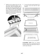
Page 49: ...t with a putty knife and unsnap it from the choke Only re move the top bottom and right sides of the choke cover at this time You will re move the handle end of the choke cover later Choke Cover Choke Door Frame 4 Place the oven door front side down on a padded surface 5 Remove the choke screws from the door frame Choke Screws Unsnap Choke Cover Electrical Shock Hazard Disconnect power before serv...

Page 50: ...knife and pry the latching tabs of the choke out of the door frame slots Lift the choke as you release the tabs so they do not snap back into the slots NOTE When you reach the handle side of door pull both the choke and the choke cover away from the door frame and then sep arate the two components REASSEMBLY NOTE When you reinstall the door on the oven insert the top pin into the pivot bracket and...

Page 51: ...4 28 NOTES ...

Page 52: ...ion before operating the microwave oven Grasp wire connectors when removing the wire leads from microwave oven parts All testing must be done with an ohmmeter having a sensitivity of 20 000 ohms per volt DC or greater and powered by at least a 9 volt battery THERMOSTATS Refer to the following pages for the procedures for accessing the thermostats Cavity Thermostat 3 page 4 5 Cavity Thermostat 2 pa...

Page 53: ... Touch the ohmmeter test leads to the following hood exhaust fan motor plug pins High Speed Red and blue wires 79 to 119 Ω High Speed Blue and black wires 22 to 43 Ω Low Speed Red and blue wires 79 to 119 Ω Low Speed Blue and white wires 43 to 62 Ω HUMIDITY SENSOR Refer to page 4 5 for the procedure for access ing the humidity sensor 1 Unplug microwave oven or disconnect power 2 Disconnect the hum...

Page 54: ...sing the motor capacitor 1 Unplug microwave oven or disconnect power 2 Discharge the capacitor by touching the leads of a 20 000 Ω resistor from each of the capacitor leads to the chassis ground 3 Disconnect the motor capacitor wires from the capacitor terminals 4 Set the ohmmeter to the R x 1 scale 5 Touch the ohmmeter test leads to the ca pacitor terminals The meter should indi cate several ohms...

Page 55: ...ally closed should read open Electrical Shock Hazard Disconnect power before servicing Replace all parts and panels before operating Failure to do so can result in death or electrical shock WARNING AC LINE FILTER Refer to page 4 12 for the procedure for ac cessing the AC line filter 1 Unplug microwave oven or disconnect power 2 Discharge the AC line filter by touching the leads of a 20 000 Ω resis...

Page 56: ...cuit Electrical Shock Hazard Disconnect power before servicing Replace all parts and panels before operating Failure to do so can result in death or electrical shock WARNING COOLING FAN MOTOR Refer to page 4 19 for the procedure for ac cessing the cooling fan motor 1 Unplug microwave oven or disconnect power 2 Disconnect one of the wires from the cooling fan motor terminals 3 Set the ohmmeter to t...

Page 57: ...ed in them and may indicate infinite resistance in both directions when testing the diode It is recommended that you use an ohmmeter with a 9 volt battery on the R x 10 scale to properly test the H V diode 1 Unplug microwave oven or disconnect power 2 Discharge the high voltage capacitor by touching the leads of a 20 000 Ω resistor from each of the capacitor leads to chas sis ground 3 Disconnect t...

Page 58: ...ITOR Electrical Shock Hazard Disconnect power before servicing Replace all parts and panels before operating Failure to do so can result in death or electrical shock WARNING MAGNETRON Refer to page 4 21 for the procedure for ac cessing the magnetron 1 Unplug microwave oven or disconnect power 2 Disconnect one of the wires from the magnetron filament terminals 3 Set the ohmmeter to the R x 1 scale ...

Page 59: ...Unplug microwave oven or disconnect power 2 Disconnect the wires from the H V trans former terminals 3 Disconnect the H V transformer wires from the magnetron and the H V capacitor 4 Set the ohmmeter to the R x 1 scale 5 Touch the ohmmeter test leads to the fol lowing H V transformer locations Filament wire org red to ground Infinite Primary terminals red white wires less than 1 Ω Secondary red wh...

Page 60: ...en or disconnect power 2 Disconnect the wires at the Primary Interlock Switch 3 Check from the common terminal black wire to the normally closed terminal orange wire Secondary Interlock 1 Unplug microwave oven or disconnect power 2 Disconnect the wires at the Secondary Interlock Switch 3 Check from the common terminal blue black wires to the normally open terminal white blue wires Monitor Interloc...

Page 61: ...ists replace electronic control 4 Replace all parts and panels before operating 5 Plug in microwave oven or reconnect power F3H Humidity sensor out of range 1 Unplug microwave oven or disconnect power 2 Connect a new sensor to the electronic control at P1 Replace all parts and panels before operating Plug in microwave oven or reconnect power 3 5 If problem persists unplug microwave oven or disconn...

Page 62: ...sition indicated in the table TOUCH PANEL AND ELECTRONIC CONTROL TEST The microwave hood combination is provided with a self diagnostic routine that can be ac cessed through the touch keypad To initiate this routine 1 Press and hold CANCEL while opening the door 2 While still holding the CANCEL button un plug the microwave oven for 2 seconds then plug it back in 3 Release the CANCEL button and clo...

Page 63: ...r in the center of the microwave oven 2 Operate on HIGH power level for 2 min utes Water should be hot NOTE If the water takes longer than 2 min utes to heat this may indicate either the oper ating voltage is lower than 110 volts or there is a problem with the microwave oven ...

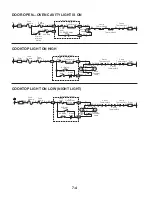
Page 64: ...R Brown OR Orange Capacitor W Exhaust Fan Thermostat 36 W 37 W 38 BU 39 BU 26 G 5P5 4P5 HL HL 27 BR 8 Y GND 43 Y G L1 L V T Prim Sec 5100 N1 HL HL Relay 4912 HL Relay 4911 GND G BK W 120V 125V 60Hz Cavity Thermostat 3 F L TTM 1 20 Amp 18 GY 24 BU 14 OR Y BK BU 13 R 30 BU FT W R HF Y BK BU 1P6 5P6 1 P3 P4 Cavity Thermostat 2 GY Gray 1 BU 2 1 CF T T 34 R 2P5 35 R 1P5 SM 19 W CL 20 W SM Stirrer Motor...

Page 65: ...ILE AT OFF OR SPEEDS 4 OR 3 Hood Exhaust Fan Motor 2 P 3 1 P 4 BU Cavity Thermostat 3 Electronic Control G BR BU Cavity Thermostat 1 L V Transformer BR 5100 Fuse 4201 BU BK Cavity Thermostat 2 HF Relay 4902 5 P 3 Y W R 5P6 BU 3 P 3 4 P 3 HF Motor Capacitor 1P6 BK BU Y R W BK BU Hood Exhaust Fan Thermostat R R Fuse 4 Amp Fuse 20 Amp L1 BK BR Filter N W BU Filter HOOD EXHAUST FAN TURNS ON LOW AUTOMA...

Page 66: ...at 2 HF Relay 4902 5P3 Y W R 5P6 4P3 HF Motor Capacitor 1P6 BK BU Y R W BK BU HF Relay 4905 BR R R Fuse 4 Amp Fuse 20 Amp L1 BK BR Filter N W BU Filter HOOD EXHAUST FAN ON SPEED 1 MANUALLY HF Triac 7103 Hood Exhaust Fan Motor 2P3 1P4 BU Cavity Thermostat 3 Electronic Control G BR BU Cavity Thermostat 1 L V Transformer 5100 Fuse 4201 BU BK Cavity Thermostat 2 HF Relay 4902 5P3 Y W R 5P6 4P3 HF Moto...

Page 67: ... BU Cavity Thermostat 3 Electronic Control G BR BU Cavity Thermostat 1 L V Transformer 5100 Fuse 4201 BU BK Cavity Thermostat 2 Hood Cooktop Lamp HL Relay 4911 1P3 Y HL Relay 4912 Diode 6106 BU W W BU 5P5 4P5 Hood Cooktop Lamp HL HL Fuse 20 Amp BR R R Fuse 4 Amp N W BU Filter L1 BK BR Filter 2P3 1P4 BU Cavity Thermostat 3 Fuse 20 Amp Electronic Control G BR BU Cavity Thermostat 1 L V Transformer 5...

Page 68: ...7 5 NOTES ...

Page 69: ...7 6 NOTES ...

Page 70: ...E PROFESSIONAL IN CANADA FOR PRODUCT SPECIFICATIONS AND WARRANTY INFORMATION CALL 1 800 461 5681 FOR TECHNICAL ASSISTANCE WHILE AT THE CUSTOMER S HOME CALL THE TECHNICALASSISTANCE LINE 1 800 488 4791 HAVE YOUR STORE NUMBER READY TO IDENTIFY YOU AS AN AUTHORIZED IN HOME SERVICE PROFESSIONAL FOR WHIRLPOOL PRODUCTS 1 800 253 1301 FOR KITCHENAID PRODUCTS 1 800 422 1230 FOR ROPER PRODUCTS 1 800 447 673...

Page 71: ......

Reviews: