background image

2-13

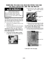
REMOVING THE HIGH VOLTAGE RECTIFIER, THE HIGH

VOLTAGE CAPACITOR, AND THE FAN MOTOR

1.

Disconnect  the  electrical  power  to  the
microwave oven.

2.

Remove the cabinet from the microwave
oven (see page 2-2 for the procedure).

CAUTION: Discharge the high voltage ca-
pacitor terminals with a 20,000 ohm resis-
tor to chassis ground.

3.

To remove the high voltage rectifier:

a) Open the cover on the mounting bracket.

CAUTION: 

When you work on the microwave

oven, be careful when handling the sheet metal
parts. Sharp edges may be present, and you
can cut yourself if you are not careful.

Electrical Shock Hazard

Disconnect power before servicing.
Replace all panels before operating.
Failure  to  do  so  could  result  in  death  or
electrical shock.

WARNING

  Cover

b) Disconnect  the  high  voltage  rectifier

lead  from  the  high  voltage  capacitor
terminal.

c) Remove the mounting screw from the

other lead of the high voltage rectifier.

To remove the high voltage capacitor & fan
motor, perform the following steps.

4.

Remove the two mounting bracket screws
from the rear panel of the microwave oven.

Continued on the next page.

  Screw

            HV Rectifier
            Lead

          HV Capacitor

  Screw

  Screw

   Rear Panel

Summary of Contents for GM8155XJB

Page 1: ...CONSUMER SERVICES TECHNICAL EDUCATION GROUP PRESENTS KM 26 JOB AID Part No 8177972 MICROWAVE CONVECTION OVEN ...

Page 2: ...er to the Use and Care Guide or Tech Sheet provided with the microwave oven The Wiring Diagrams and Strip Circuits used in this Job Aid are typical and should be used for training purposes only Always use the Wiring Diagram supplied with the product when servicing the unit GOALS AND OBJECTIVES The goal of this Job Aid is to provide detailed information that will enable the service technician to pr...

Page 3: ...r And The Fan Motor 2 13 Removing The Convection Thermistor Circulation Motor Convection Element 2 15 Removing The Turntable Motor 2 18 Removing The Oven Door The Switch Actuators And The Outer Glass 2 19 COMPONENT TESTING 3 1 The Turntable And Damper Motors 3 1 The Fan And Circulation Motors 3 2 The Line Fuse High Voltage Rectifier Diode High Voltage Capacitor 3 3 The Convection Element Humidity ...

Page 4: ...FEET 04 4 CU FT 10 1 0 CU FT 06 6 CU FT 12 1 2 CU FT 07 7 CU FT 14 1 4 CU FT 08 8 CU FT 15 1 5 CU FT 09 9 CU FT 16 1 6 CU FT FEATURE LEVEL 0 30 KIT IF KIT 2 22 KIT IF KIT 4 24 KIT IF KIT 5 SENSORED MODEL 7 27 KIT IF KIT FEATURE CODE C CSA APPROVED S CARRY IN WARRANTY EFFECTIVE 02 96 X IN HOME WARRANTY EFFECTIVE O2 96 YEAR OF INTRODUCTION J 2000 K 2001 L 2002 COLOR CODE B BLACK Q WHITE T BISCUIT EN...

Page 5: ... v MODEL SERIAL NUMBER LABEL AND TECH SHEET LOCATIONS The Model Serial Number label and Tech Sheet locations are shown below Tech Sheet Location Model Serial Number Location ...

Page 6: ... shock by providing an escape wire for the electrical current The microwave oven is equipped with a cord having a grounding wire with a grounding plug The plug must be plugged into an outlet that is properly installed and grounded Improper use of the grounding plug can result in a risk of electric shock Consult a qualified electrician or serviceman if the grounding instructions are not completely ...

Page 7: ...alling the magnetron Routine service safety procedures should be exercised at all times Untrained personnel should not attempt service without a thorough review of test procedures and safety information contained in this Job Aid Whirlpool microwave ovens have a monitoring system designed to assure proper operation of the safety interlock systems The interlock monitor switch will immediately cause ...

Page 8: ...Dropping or Abuse 3 Before turning on the microwave power for any service test or inspection within the microwave generating components check the magnetron wave guide or transmission line and cavity for proper alignment 4 Any defective or misadjusted components in the interlock monitor door seal and microwave generation and transmission system shall be repaired by procedures described in the Job A...

Page 9: ...rew does not ground the appliance unless the cover screw is metal and not insulated and the wall receptacle is grounded through the house wiring CAUTION Disconnect the oven from electrical sup plybeforeservicing Failuretodosocould result in electrical shock or death Improper use of the grounding plug can result in a risk of electrical shock Do not under any circumstance cut or remove the third gro...

Page 10: ...formance Standard for Microwave Ovens A properly operating door and seal assembly will normally register small emissions but they must be no greater than 4 mw cm2 to allow for measurement uncertainty NOTE Enter leakage readings in space BE FORE and AFTER on the service document All microwave ovens exceeding the emission level of 4 mw cm2 must be reported to Dept of Service for microwave ovens imme...

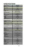
Page 11: ...VECTION COOKING CYCLES Auto Cook Whirlpool Corporate Exclusive Auto Convection Recipes 41 Recipes using optimal combination of Convection and or Microwaves Meat 8 options Doneness Selection Auto Convection Meat category only Rare Med Rare Med Med Well Well Poultry 6 options Fish 5 options Baked Goods 9 options Other Dishes 7 options Snack Foods 6 options OPERATING FEATURES Minute Timer Independent...

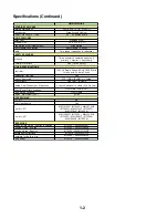
Page 12: ...al Use Only Yes Agency Approvals FCC CDRH DHHS U L listed Full Warranty One Year In Home Limited Addl Warranty on Magnetron 4 Years Additional In Home 2nd 5th year Model Serial Plate Location Front Plate Lower Left Cook Guide Location Front Frame Approx Net Weight Lbs 52 lbs ACCESSORIES UTC Kit No Over Heat Source Yes Trim Kit 27 MK1157XJQ 8172230 MK1157XJB 8172231 MK1157XJT 8172232 MK1157XJS 8172...

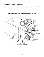
Page 13: ...ocations are shown below MICROWAVE OVEN COMPONENT LOCATIONS Turntable Motor H V Transformer Damper Switch H V Rectifier Diode H V Capacitor Damper Motor Magnetron Fan Motor Line Fuse Humidity Sensor Secondary Interlock Switch Primary Interlock Switch Monitor Interlock Switch Oven Thermostat Oven Lamp Circulation Motor Convection Element Convection Thermistor ...

Page 14: ...or CAUTION When you work on the microwave oven becarefulwhenhandlingthesheetmetal parts Sharp edges may be present and you can cut yourself if you are not careful WARNING 3 Remove the five rear flange screws and the two right side screws from the micro wave oven cabinet NOTE The two bot tom flange screws are T 20 tamper resis tant torx screws Side Screws Two T 20 Tamper Resistant Torx Screws Top S...

Page 15: ...al Shock Hazard Disconnect power before servicing Replace all panels before operating Failure to do so could result in death or electrical shock WARNING 5 From the front of the unit slide the elec tronic oven control up unhook the four side tabs from the chassis slots and pull the EOC forward 6 Disconnect the wire connectors from the EOC board 7 To remove the circuit board from the EOC panel a Lif...

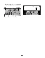
Page 16: ...2 4 b Remove the three screws and unclip the board from the two locking arms Screw Screw Screw Locking Arm Locking Arm EOC Board ...

Page 17: ...u can cut yourself if you are not careful Electrical Shock Hazard Disconnect power before servicing Replace all panels before operating Failure to do so could result in death or electrical shock WARNING b Carefully pull out on the switch while you raise the locking arm and remove the switch from the plastic holder Pull Out Raise Locking Arm 3 To remove the primary door interlock switch a Disconnec...

Page 18: ...e switch in the next step be careful not to press in too far or you will break the arm off If this hap pens you will have to replace the entire switch bracket b Pressinonthelockingarm refertothe previous photo rotate the switch so it isfreeofthearm andpull theswitch off the pivot pin Rotate Pivot Pin Wire Connectors Monitor Switch Locking Arm Locking Arm Secondary Switch ...

Page 19: ...ront of the top cover and bend the two clips out just enough to remove the humidity sensor cable from them 6 Disconnect humidity sensor connector CN4fromtheelectronicovencontrolboard Electrical Shock Hazard Disconnect power before servicing Replace all panels before operating Failure to do so could result in death or electrical shock WARNING 4 Remove the mounting screw from the humidity sensor lif...

Page 20: ...connect power before servicing Replace all panels before operating Failure to do so could result in death or electrical shock WARNING c Pull the oven lamp out of the unit 4 To remove the damper motor a Disconnect the wire connector from the motor terminals b Remove the two mounting screws REASSEMBLY NOTE When you reinstall the damper motor align the flat of the motor shaft with the flat of the air...

Page 21: ...ou can cut yourself if you are not careful Electrical Shock Hazard Disconnect power before servicing Replace all panels before operating Failure to do so could result in death or electrical shock WARNING 4 Remove the two indicated screws from the damper motor housing 5 Pull the damper motor housing out and remove the oven thermostat 3 Disconnect the wire connectors from the oven thermostat termina...

Page 22: ...ful Electrical Shock Hazard Disconnect power before servicing Replace all panels before operating Failure to do so could result in death or electrical shock WARNING 3 Disconnect the filament connector from the magnetron terminals 4 Remove the wire strap screw and the four magnetron mounting screws and remove the magnetron from the waveguide Mag Screws Mag Screws Filament Connector Strap Screw Magn...

Page 23: ...Position the microwave oven on its left side so that the bottom of the oven is accessible 6 Remove the four high voltage transformer mounting screws from the bottom of the oven Hold the transformer with one hand to keep it from falling HV Transformer Mounting Screws HV Transformer HV Capacitor Secondary Connectors Primary Connectors HV Transformer Filament Connector 3 Disconnect the two primary wi...

Page 24: ...may be present and you can cut yourself if you are not careful Electrical Shock Hazard Disconnect power before servicing Replace all panels before operating Failure to do so could result in death or electrical shock WARNING Wire Connector 20A Fuse 3 Disconnect the two wire connectors from the line fuse terminals 4 Unsnap the 20A line fuse from the fuseholder 5 Remove the screw from the fuseholder ...

Page 25: ...hesheetmetal parts Sharp edges may be present and you can cut yourself if you are not careful Electrical Shock Hazard Disconnect power before servicing Replace all panels before operating Failure to do so could result in death or electrical shock WARNING Cover b Disconnect the high voltage rectifier lead from the high voltage capacitor terminal c Remove the mounting screw from the other lead of th...

Page 26: ...citor a Disconnect the high voltage rectifier lead from the terminal of the high volt age capacitor b Remove the clamp screw and remove the high voltage capacitor from the bracket HV Rectifier Terminal HV Capacitor Clamp Screw Fan 5 Disconnect the wire connectors from the line fuse terminals the fan motor and the high voltage capacitor and remove the bracket assembly Fan Motor HV Cap Bracket Assem...

Page 27: ...f you are not careful Electrical Shock Hazard Disconnect power before servicing Replace all panels before operating Failure to do so could result in death or electrical shock WARNING 4 To remove the circulation motor a If not already done remove the rear convection cover see steps 3a 3b b Remove the four 7 mm hex washer nuts from the convection mounting cover removethecoverfromthestuds and lean it...

Page 28: ...an motor mounting bracket screws and remove the motor and bracket e Remove the 7 mm nut split washer flat washer and outer fan from the circula tion motor shaft Spacer Inner Fan Wire Connectors Circulation Motor Screws Screw REASSEMBLY NOTE Make sure that you mount the circulation motor on the bracket with the two bracket holes to the left and the motor coil positioned up as shown above c Remove t...

Page 29: ...2 17 e Remove the two mounting screws from the convection element brackets and remove the element Convection Element Screws ...

Page 30: ...wer before servicing Replace all panels before operating Failure to do so could result in death or electrical shock WARNING Turntable Motor Cover 6 Remove the wire connector from the turn table motor terminals and then remove the two screws 5 Use a pair of wire cutters and clip the six areas between the holes on the turntable motor cover and remove the cover Turntable Spindle 4 Turn the microwave ...

Page 31: ... servicing Replace all panels before operating Failure to do so could result in death or electrical shock WARNING 3 To remove the oven door a Lift the door and remove the bottom hinge pin from its bracket hole then lower the door and remove the top hinge pin from its bracket hole b Use a putty knife and pry out along the inner edge of the choke cover c Pull out on the cover to release all of the l...

Page 32: ...ng tabs along the bottom and right sides of the inner door frame while you lift the frame c When the inner door frame is free of the tabs slide the frame out of the 3 top holders and remove it e Unhook the actuators from the slots in the inner door frame Door Frame Screw 1 of 2 Inner Door Frame Unclip 3 Tabs Start Here Slide Out Of Holders Unclip 3 Tabs Unhook Spring Switch Actuators Hook Hook ...

Page 33: ...he outer glass a Use a screwdriver and push the 10 locking tabs see the arrows below back so they are not over the glass Tab Pushed Back Tab Over Outer Glass Outer Glass b Lift the glass and remove it from the door frame ...

Page 34: ...2 22 NOTES ...

Page 35: ...turntable motor 1 Disconnect the electrical power to the microwave oven 2 Disconnect the wires from the turntable motor terminals 3 Set the ohmmeter to the R x 1 scale 4 Touch the ohmmeter leads to the motor terminals Themetershouldindicate25Ω TURNTABLE MOTOR Electrical Shock Hazard Disconnect power before servicing Replace all panels before operating Failure to do so could result in death or elec...

Page 36: ... the R x 1 scale 4 Touch the ohmmeter leads to the motor terminals The meter should indicate ap proximately 30 Ω Electrical Shock Hazard Disconnect power before servicing Replace all panels before operating Failure to do so could result in death or electrical shock WARNING Refer to page 2 13 for the procedure for servic ing the fan motor 1 Disconnect the electrical power to the microwave oven 2 Di...

Page 37: ...gh voltage capacitor terminals b Set the ohmmeter to the R x 10K scale c Touch the ohmmeter leads to the ca pacitor terminals The meter should in dicate several thousand ohms and gradually return to infinity Line Fuse W Fuseholder Refer to page 2 12 for the procedure for servic ing the line fuse and page 2 13 for the high voltage rectifier diode and high voltage ca pacitor 1 Disconnect the electri...

Page 38: ...nels before operating Failure to do so could result in death or electrical shock WARNING Refer to page 2 7 for the procedure for servic ing the humidity sensor 1 Disconnect the electrical power to the microwave oven 2 Disconnect the humidity sensor connec tor from the electronic oven control at CN4 3 Set the ohmmeter to the R x 1K scale 4 Touch the ohmmeter leads to the follow ing wires at the con...

Page 39: ...connect power before servicing Replace all panels before operating Failure to do so could result in death or electrical shock WARNING Refer to page 2 9 for the procedure for servic ing the oven thermostat 1 Disconnect the electrical power to the microwave oven 2 Disconnect the wires from the oven ther mostat terminals 3 Set the ohmmeter to the R x 1 scale 4 Touch the ohmmeter leads to the thermo s...

Page 40: ...high voltage capacitor and mag netron 3 Disconnect the two wires from the primary terminals 4 Set the ohmmeter to the R x 1 scale 5 Touch the ohmmeter leads to the two primary terminals The meter should indi cate between 3 and 6 Ω 6 Touch the ohmmeter leads to the two filamentwireconnectors Themetershould indicate less than 1 Ω 7 Touch one ohmmeter lead to the red with a black stripe secondary wir...

Page 41: ...h Disconnect the wire connector from the terminals b With the door closed touch the ohm meter leads to the switch terminals The meter should indicate 0 Ω continuity c With the door open touch the ohmme ter leads to the switch terminals The meter should indicate infinity no conti nuity a Monitor switch Disconnect the wires from the terminals b With the door closed touch the ohm meter leads to the s...

Page 42: ...3 8 NOTES ...

Page 43: ... to 77 F 25 C tap water 2 Place the cup of water in the center of the oven 3 Operate the microwave oven at HIGH power 4 The water should boil within 3 1 2 to 4 minutes NOTE Times longer than 4 minutes may indi cate that the operating voltage is lower than 110 volts or that there is a problem with the oven SENSOR POPCORN SENSOR REHEAT SENSOR COOK WARM HOLD TIMER SET OFF CLOCK SET DEFROST OPTIONS N ...

Page 44: ...r programmed operation is still running The time was not set after touching the MICRO keypad The electrical supply to the wall outlets is low or is lower than normal Check to find out if the line voltage is low The COOK POWER is not at the recommended setting Larger amounts of food need longer cooking times The turntable is not correctly in place Make sure that the turntable has the correct side f...

Page 45: ... T M L V Transformer Turntable Motor CN1 CN2 RD RD RD RD BK H V Rectifier Diode H V Capacitor BN BL RD WH WH WH WH YL YL WH BL Fan Motor Damper Motor Circulation Motor Convection Heater Damper Switch Primary Interlock Switch Secondary Interlock Switch Monitor Switch 1 3 5 7 9 3 4 2 1 PK GN GN YL YL WH Thermistor Humidity Sensor RD BK CN4 CN5 H V Transformer Magnetron 1 2 3 1 2 3 1 1 2 2 3 3 4 4 N ...

Page 46: ...rimary Interlock Switch Oven Lamp Relay 1 Relay 2 Relay 6 Line Fuse 20A L N BK WH RD RD BK BK WH RD WH BK YL RD YL BU WH WH WH YL BL PK RD BN BK BL BK BL BL Convection Heater WH D M F M C M T T M L V Transformer Oven Thermostat Relays Primary Interlock Switch Oven Lamp Relay 1 Relay 2 Line Fuse 20A L N BK RD WH WH BK BK WH BK YL RD PK RD BN BK BL BL BL High Voltage Section WH D M F M T T M L V Tra...

Page 47: ...mostat Relay 2 Primary Interlock Switch Secondary Interlock Switch Monitor Switch Line Fuse 20A L N BK WH WH BN BK BN BK WH Oven Thermostat Relay 2 Primary Interlock Switch Secondary Interlock Switch Monitor Switch Line Fuse 20A L N BK WH WH BN BK BN BK WH ...

Page 48: ...5 4 NOTES ...

Page 49: ...iances Installation information Accessory and repair parts sales Specialized customer assistance Spanish speaking hearing impaired limited vision etc Referrals to local dealers service compa nies and repair parts distributors Whirlpool designated service technicians are trained to fulfill the product warranty and pro vide after warranty service anywhere in the United States To locate the Whirlpool...

Page 50: ...om anywhere in the U S A FSP Replace ment parts and repair labor costs to correct defects in materials or workmanship Service must be provided by a Whirlpool desig nated servicing company FSP Replace ment magnetron tube on micro wave convection ovens if defective in materials or workmanship A Service calls to 1 Correct the installation of the microwave convection oven 2 Instruct you how to use the...

Page 51: ...CORPORATION ...

Reviews: