background image

6" (15.2 cm) vent system = 73 ft (22.2 m) total

A                                                                  B

C                    


D

6 ft (1.8 m)

2 ft

(0.6 m)

A. Two 90° elbows = 20 ft (6.1 m)
B. 1 wall cap = 40 ft (12.2 m)
C. 1 rectangular to round transition 
     piece = 5 ft (1.5 m)
D. 2 ft (0.6 m) + 6 ft (1.8 m) 


straight = 8 ft (2.4 m)

29

" (76.0 cm)

15

"

(40.0 cm)

17

"

(43.8 cm)

16

"

(41.3 cm)

PRODUCT MODEL NUMBERS

PRODUCT DIMENSIONS

VENTING REQUIREMENTS

Electrical:

A 120-Volt, 60-Hz, AC-only, 15- or 20-amp fused electrical

supply with a fuse or circuit breaker. A time-delay fuse or time-delay circuit
breaker is recommended. It is recommended that a separate circuit serving
only this microwave oven be provided.

Microwave Hood Combination

Because Whirlpool Corporation policy includes a continuous commitment to improve
our products, we reserve the right to change materials and specifications without notice.

Dimensions are for planning purposes only.  For complete details, see Installation
Instructions packed with product.  Specifications subject to change without notice.

Ref. W10247296B

8/15/12

CABINET OPENING DIMENSIONS

A 3

¹⁄₄

" x 10" (8.3 x 25.4 cm) rectangular or 6" (15.2 cm) round vent should be used.

The total length of the vent system including straight vent, elbow(s), transitions and wall
or roof caps must not exceed the equivalent of 140 ft (42.7 m) for either type of vent. 
For best performance, use no more than three 90° elbows.
To calculate the length of the system you need, add the equivalent length for each vent
piece used in the system. See the following examples:

A. Rectangular to round transition piece: 3 " x 10" to 6" = 5 ft

(8.3 x 25.4 cm to 15.2 cm = 1.5 m)

B. Roof cap: 3 " x 10" = 24 ft (8.3 x 25.4 cm = 7.3 m)
C. 90° elbow: 3 " x 10" = 25 ft (8.3 x 25.4 cm = 7.6 m)
D. 90° elbow: 6" = 10 ft (15.2 cm = 3 m)

E. Wall cap: 3 " x 10" = 40 ft (8.3 x 25.4 cm = 12.2 m)
F. 45° elbow: 6" = 5 ft (15.2 cm = 1.5 m)

G. 90° flat elbow: 3 " x 10" = 10 ft (8.3 x 25.4 cm = 3 m)

A                           B                            C

D                  E                    F               G

3 " x 10" (8.3 x 25.4 cm) vent system = 73 ft (22.2 m) total

A. One 3 " x 10" (8.3 x 25.4 cm) 90° elbow = 25 ft (7.6 m)
B. 1 wall cap = 40 ft (12.2 m)

C. 2 ft (0.6 m) + 6 ft (1.8 m) straight = 8 ft (2.4 m)

A                                          B

C

6 ft (1.8 m)

2 ft

(0.6 m)

Rectangular to Round Transition for Roof Venting

NOTE:

 The minimum 3" (7.6 cm) clearance must exist between 

the top of the microwave oven and the rectangular to round 
transition piece so that the damper can open freely and fully.

A

B

C

E

F

D

3" (7.6 cm)

A. Roof cap
B. 6" (15.2 cm) min. diameter round vent

C. Elbow (for wall venting only)
D. Wall cap

E. 3 " x 10" to 6" (8.3 x 25.4 cm to 15.2 cm) 

rectangular to round transition piece

F. Vent extension piece, at least 3" (7.6 cm) high

12" (30.5 cm) min.
14" (35.6 cm) max.

30"

(76.2 cm)

min.

A                   B

upper cabinet and 
side cabinet depth

30"

(76.2 cm)

typical*

66" (167.6 cm) min.

The grounded 3-prong outlet must be inside the upper cabinet.

A. 2" x 4" wall stud
B. Grounded 3-prong outlet

*30" (76.2 cm) is typical for 66" (167.6 cm) installation height. 

Exact dimensions may vary depending on type of range/cooktop below.

GMH3204XV
GMH5205XV
GMH6185XV
WMH1162XV
WMH1163XV
WMH1164XW

WMH2175XV
WMH2205XV
WMH3205XV
WMH31017A
WMH32517A
WMH53520A

WMH32L19A
WMH73L20A
WMH75520A
WMH76718A

Summary of Contents for GMH3204XV

Page 1: ...ach vent piece used in the system See the following examples A Rectangular to round transition piece 3 x 10 to 6 5 ft 8 3 x 25 4 cm to 15 2 cm 1 5 m B Roof cap 3 x 10 24 ft 8 3 x 25 4 cm 7 3 m C 90 elbow 3 x 10 25 ft 8 3 x 25 4 cm 7 6 m D 90 elbow 6 10 ft 15 2 cm 3 m E Wall cap 3 x 10 40 ft 8 3 x 25 4 cm 12 2 m F 45 elbow 6 5 ft 15 2 cm 1 5 m G 90 flat elbow 3 x 10 10 ft 8 3 x 25 4 cm 3 m A B C D ...

Page 2: ...ounting Plate to Wall 8 Prepare Upper Cabinet 8 Install Damper Assembly 9 Install the Microwave Oven 9 Complete Installation 10 VENTING DESIGN SPECIFICATIONS 11 ASSISTANCE 12 Replacement Parts 12 Accessories 12 W10247296B You can be killed or seriously injured if you don t immediately You can be killed or seriously injured if you don t follow All safety messages will tell you what the potential ha...

Page 3: ...ar a left sidewall make sure there is at least 6 15 2 cm of clearance between the wall and the microwave oven so that the door can open fully Some cabinet and building materials are not designed to withstand the heat produced by the microwave oven for cooking Check with your builder or cabinet supplier to make sure that the materials used will not discolor delaminate or sustain other damages Speci...

Page 4: ...tlet Do not remove ground prong Do not use an adapter Do not use an extension cord Failure to follow these instructions can result in death fire or electrical shock WARNING GROUNDING INSTRUCTIONS SAVETHESE INSTRUCTIONS For all cord connected appliances The microwave oven must be grounded In the event of an electrical short circuit grounding reduces the risk of electric shock by providing an escape...

Page 5: ...ation installation Keep the damper assembly in case the venting method is changed or the microwave oven is reinstalled in another location where wall or roof venting may be used Wall Venting Installation Only 1 Remove screws attaching damper plate to top of microwave oven exterior Slide damper plate toward the front of the microwave oven and lift up 2 Keep damper plate and screws together and set ...

Page 6: ... is not positioned with flat sides facing the back of the microwave oven as shown performance will be poor 6 Reattach blower motor to back of microwave oven with 2 screws removed in Step 3 of Wall Venting Installation Only Securely tighten screws NOTE If blower motor is not correctly oriented the 2 screws removed in Step 3 cannot be reattached to the microwave oven 7 Reattach damper plate Make sur...

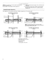
Page 7: ...ctions show examples of preferred installation configurations with the mounting plate No Wall Studs at End Holes Figure 1 No Wall Studs at End Holes Figure 2 NOTE If wall stud is within 6 15 2 cm of the vertical centerline see Mark Rear Wall section only recirculation or roof venting installation can be done Wall Stud at One End Hole Figure 3 Wall Studs at Both End Holes Figure 4 A End holes on mo...

Page 8: ...losest to the wall stud centerline s See figures 1 2 and or 3 in Possible Wall Stud Configurations in Locate Wall Stud s section The blackened holes in the shaded areas are ideal hole locations 7 Set the mounting plate aside Wall Venting Installation Only 8 Mark the centerline 3 8 1 cm down from the bottom edge of the upper cabinet 9 Using measuring tape measure out 6 15 2 cm on both sides of the ...

Page 9: ...ed in Step 3 of Installation for Wall Stud at One End Hole in the Drill Holes in Rear Wall section 2 Start a toggle nut on the bolt from the back of the mounting plate Leave enough space for the toggle nut to go through the wall and to open 3 Position mounting plate on the wall 4 Push the bolt with toggle nut through the drywall and finger tighten the bolt to make sure toggle nut has opened agains...

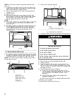
Page 10: ...e of the microwave oven is the heavy side Handle the microwave oven gently 1 Place a washer on each 1 4 20 x 3 flat head bolt and place inside upper cabinet near the 3 8 10 mm holes 2 Make sure the microwave oven door is closed and taped shut 3 Using 2 or more people lift microwave oven and hang it on support tabs at the bottom of mounting plate NOTE To avoid damage to the microwave oven do not gr...

Page 11: ...ecure with sheet metal screw NOTE The screw cannot be installed if the damper assembly is not positioned as shown 2 Connect vent to damper assembly Complete Installation 1 Install filters Refer to the User Instructions for filter placement 2 Plug microwave oven into grounded 3 prong outlet 3 Reconnect power 4 Check the operation of microwave oven by placing 1 cup 250 mL of water on the turntable a...

Page 12: ... the damper to open fully If venting through the roof and rectangular to round transition is used be sure there is at least 3 7 6 cm of clearance between the top of the microwave oven and the transition piece See Rectangular to Round Transition illustration Rectangular to Round Transition NOTE The minimum 3 7 6 cm clearance must exist between the top of the microwave oven and the rectangular to ro...

Page 13: ...ven If you need additional assistance call us at our toll free number or visit our website listed in the User Instructions Replacement Parts If any of the installation hardware needs to be replaced call us at our toll free number listed in the User Instructions Following is a list of available replacement parts You will need your model number located on the front facing of the microwave oven openi...

Page 14: ...the safety of others are very important We have provided many important safety messages in this manual and on your appliance Always read and obey all safety messages This is the safety alert symbol This symbol alerts you to potential hazards that can kill or hurt you and others All safety messages will follow the safety alert symbol and either the word DANGER or WARNING These words mean follow ins...

Page 15: ...er edge of table or counter See door surface cleaning instructions in the Microwave Oven Care section To reduce the risk of fire in the oven cavity Do not overcook food Carefully attend the microwave oven when paper plastic or other combustible materials are placed inside the oven to facilitate cooking Remove wire twist ties from paper or plastic bags before placing bags in oven If materials insid...

Page 16: ...e oven must be grounded In the event of an electrical short circuit grounding reduces the risk of electric shock by providing an escape wire for the electric current The microwave oven is equipped with a cord having a grounding wire with a grounding plug The plug must be plugged into an outlet that is properly installed and grounded WARNING Improper use of the grounding plug can result in a risk o...

Page 17: ...ools the fan will automatically decrease its speed then turn off Light Timer Set the cooktop light to turn on and off at certain times Touch OPTIONS CLOCK to reach the Light Timer submenu and follow the prompts to set the light on time and light off time in hours and minutes or to cancel Light Timer NOTE Light Timer uses 12 hour clock only Filter Reset Reset the filter status after replacing and o...

Page 18: ... stage then enter the cook time and cook power of each then touch the Start control Sensor Cooking A sensor in the microwave oven detects moisture released from food as it heats and adjusts the cooking time accordingly Make sure microwave oven has been plugged in for at least 1 minute Use microwave safe dish with loose fitting lid or cover microwave safe dish with plastic wrap and vent For optimal...

Page 19: ...he tab area and drop out the filter To reinstall place end of the filter into the opening opposite the tab area swing up the other end and slide it toward the tab area Charcoal filter The charcoal filter is behind the vent grille at the top front of the microwave oven The charcoal filter cannot be cleaned and should be replaced about every 6 months or as prompted by filter status indicator Remove ...

Page 20: ...owave oven Check the following Soil buildup Soil buildup on cavity walls microwave inlet cover cooking rack supports and area where the door touches the frame can cause arcing See General Cleaning in Microwave Oven Care section Turntable alternates rotation directions This is normal and depends on motor rotation at the beginning of the cycle Display shows messages Enter clock with flashing digits ...

Page 21: ...sportation for product service if your major appliance is located in a remote area where service by an authorized Whirlpool servicer is not available 10 The removal and reinstallation of your major appliance if it is installed in an inaccessible location or is not installed in accordance with published installation instructions 11 Major appliances with original model serial numbers that have been ...

Reviews: