background image

Summary of Contents for GY399LXUB03

Page 1: ... Engaged 13 Level Range 14 Complete Installation 14 Moving the Range 15 SleCURITle DE LA CUISINIERE 16 EXIGENCES D INSTALLATION 17 Outillage et pieces 17 Exigences d emplacement 17 Specifications electriques 19 Preparation du plan de travail 19 INSTRUCTIONS D INSTALLATION 20 Deballage de la cuisiniere 20 Reglage des pieds de nivellement 20 Installation de la bride antibasculement 21 Verifier que l...

Page 2: ...tial hazard is tell you how to reduce the chance of injury and tell you what can happen if the instructions are not followed Tip Over Hazard A child or adult can tip the range and be killed Install anti tip bracket to floor or wall per installation instructions Slide range back so rear range foot is engaged in the slot of the anti tip bracket Re engage anti tip bracket if range is moved Do not ope...

Page 3: ...e in the kitchen To eliminate the risk of burns or fire by reaching over heated surface units cabinet storage space located above the surface units should be avoided If cabinet storage is to be provided the risk can be reduced by installing a range hood that projects horizontally a minimum of 5 12 7 cm beyond the bottom of the cabinets Cabinet opening dimensions that are shown must be used Given d...

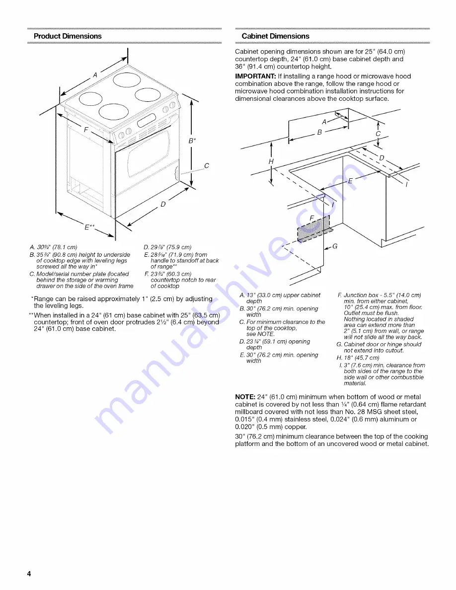
Page 4: ...owave hood combination installation instructions for dimensional clearances above the cooktop surface H F A 13 33 0 cm upper cabinet depth B 30 76 2 cm min opening width C For minimum clearance to the top of the cooktop see NOTE D 23 59 1 cm opening depth E 30 76 2 cm min opening width F Junction box 5 5 14 0 cm min from either cabinet 10 25 4 cm max from floor Outlet must be flush Nothing located...

Page 5: ...model serial number rating plate The model serial rating plate is located on the side of the oven frame behind the storage drawer or warming drawer panel Refer to the figures in Product Dimensions in the Location Requirements section This range is manufactured with the neutral terminal connected to the cabinet Use a 3 wire UL listed 40 or 50 amp power supply cord pigtail See the following Range Ra...

Page 6: ...aker is recommended This range is equipped with a CSA International Certified Power Cord intended to be plugged into a standard 14 50R wall receptacle Be sure the wall receptacle is within reach of range s final location Do not use an extension cord The cooktop sides of the slide in range fit over the cutout edge of your countertop If you have a square finish flat countertop and the opening width ...

Page 7: ...ed Failure to follow these instructions can result in death or serious burns to children and adults 2 Adjust the leveling legs to the correct height Leveling legs can be loosened to add up to a maximum of 1 2 5 cm A minimum of 3Ae 5 mm is needed to engage the anti tip bracket NOTE If height adjustment is made when range is standing tilt the range back to adjust the front legs then tilt forward to ...

Page 8: ...hock 1 2 3 Disconnect power Use Phillips screwdriver to remove the terminal block cover screw located on the back of the range Pull cover down and toward you to remove cover Remove plastic tag holding three 10 32 hex nuts from the middle post of the terminal block 4 Add strain relief Style 1 Power supply cord strain relief Assemble a UL listed strain relief in the opening A b xs J _ _ 5 _ _ A UL l...

Page 9: ...duit plate down and out Position cord conduit plate as shown in the following illustration A Removable retaining nut B Strain relief Feed the flexible conduit through the strain relief allowing enough slack to easily attach wiring to the terminal block Tighten strain relief screw against the flexible conduit 5 6 Replace back panel and screws on rear of range Complete installation following instruc...

Page 10: ...attach the wiring to the terminal block C D A Terminal block B Ground link screw C Cord conduit plate D Power supply cord wires 4 Use Phillips screwdriver to connect the green ground wire from the power supply cord to the range with the ground link screw The ground wire must be attached first 5 Use 3 8 nut driver to connect the neutral white wire to the center terminal block post with one of the 1...

Page 11: ...meter connection opening with ring terminals and marked for use with ranges 5 Replace terminal block access cover Direct Wire Installation Copper or Aluminum Wire This range may be connected directly to the fuse disconnect or circuit breaker box Depending on your electrical supply make the required 3 wire or 4 wire connection 1 Strip outer covering back 3 7 6 cm to expose wires Strip the insulatio...

Page 12: ...F Line 2 red G Terminal lug 7 Connect line 1 black and line 2 red wires to the outer terminal block posts with 10 32 hex nuts 8 Securely tighten hex nuts 9 Replace terminal block access cover 3 wire connection Direct Wire Use this method only if local codes permit connecting ground conductor to neutral supply wire 1 Pull the conduit through the hole and conduit plate on bottom of range Allow enoug...

Page 13: ... On models with a storage drawer 1 2 3 Remove the storage drawer Use a flashlight to look underneath the bottom of the range Visually check that the rear range foot is inserted into the slot of the anti tip bracket On models with a warming drawer 1 Place the outside of your foot against the bottom front of the warming drawer to keep the range from moving and grasp the control panel with two hands ...

Page 14: ...must be level for satisfactory baking performance 1 Check that all parts are now installed If there is an extra part go back through the steps to see which step was skipped 2 Check that you have all of your tools 3 Dispose of recycle all packaging materials 4 Check that the range is level See Level Range 5 Use a mild solution of liquid household cleaner and warm water to remove waxy residue caused...

Page 15: ...e For power supply cord connected ranges 1 Slide range forward 2 Unplug the power supply cord 3 Complete cleaning or maintenance 4 Plug in power supply cord 5 Slide range back so rear range foot is under anti tip bracket For direct wired ranges Electrical Shock Hazard Disconnect power before servicing Replace all parts and panels before operating Failure to do so can result in death or electrical ...

Page 16: ... non respect des instructions Risque de basculement Un enfant ou une personne adulte peut faire basculer la cuisini_re ce qui peut causer un d_cbs Fixer la bride antibasculement au plancher ou au mur conform_ment aux instructions d installation Faire glisser de nouveau la cuisinibre de fa_on a ce que le pied arribre de la cuisinibre se trouve dans la fente de la bride antibasculement R_engager la ...

Page 17: ...ntalement sur un minimum de 5 12 7 cm au del du bas des armoires Respecter les dimensions indiqu_es pour les ouvertures decouper dans les placards ces dimensions constituent les valeurs minimales des degagements de separation La bride antibasculement doit _tre installee Pour I installation de la bride antibasculement expediee avec la cuisiniere voir la section Installation de la bride antibasculem...

Page 18: ...dimensions de degagement respecter au dessus de la surface de la table de cuisson F A Profondeur des placards sup6rieurs 13 33 0 cm B Largeur de I ouverture 30 76 2 cm min C Pour la distance fibre minimale vers la partie sup_rieure de la table de cuisson voir la REMARQUE D Profondeur d ouverture 23 59 1 cm E Largeur de I ouverture 30 76 2 cm min E Bo e dejonction 5 5 14 cm min depuis I un des deux...

Page 19: ...es qui specifient une utilisation avec une ouverture pour le raccordement d un diametre nominal de 1 34 9 mm On recommande I emploi de fusibles temporises ou disjoncteurs Cette cuisiniere est dotee d un cordon d alimentation homologation CSA International destine _tre branche sur une prise de courant murale standard 14 50R Veiller ace que la prise de courant murale soit placee a portee de la posit...

Page 20: ...eure ou qu elle est supportee par 2 pieds apres avoir t replacee en position verticale REMARQUE Pour placer _ nouveau la cuisiniere en position verticale placer un carton ou un panneau de fibres dur devant la cuisiniere _ I aide de deux personnes ou plus relever la cuisiniere et la placer sur le carton ou le panneau de fibres dur Risque de basculement Un enfant ou une personne adulte peut faire ba...

Page 21: ...pecter le dessous de la cuisiniere 3 Inspecter la cuisiniere pour verifier que le pied arriere de la cuisiniere se trouve dans la fente de la bride antibasculement Sur les modules avec tiroir r_chaud 1 Placer I exterieur du pied contre la partie inferieure avant du tiroir rechaud pour emp_cher la cuisiniere de bouger et saisir le tableau de commande a deux mains tel qu indiqu 2 Tenter d incliner l...

Page 22: ... pour que la performance de cuisson au four soit satisfaisante 1 Verifier que toutes les pieces sont maintenant installees S il reste une piece passer en revue les differentes etapes pour decouvrir laquelle aurait ete oubliee 2 Verifier la presence de tousles outils 3 deter recycler tous les materiaux d emballage 4 Verifier que la cuisini re est d aplomb Voir Fleglage de I aplomb de la cuisini re ...

Page 23: ...ent aux instructions d installation Faire glisser de nouveau la cuisiniere de fa on a ce que le pied arriere de la cuisiniere se trouve dans la fente de la bride antibasculement R_engager la bride antibasculement si la cuisiniere a _t_ d_plac_e Ne pas faire fonctionner la cuisiniere si la bride antibasculement n est pas install_e et engag_e Le non respect de ces instructions peut causer un d_cbs o...

Page 24: ...W10430949B 2012 Whirlpool Corporation All rights reserved Used under license in Canada Tous droits reserves Utilisee sous licence au Canada 12 12 Printed in U S A Imprime aux E U ...

Reviews: