background image

8

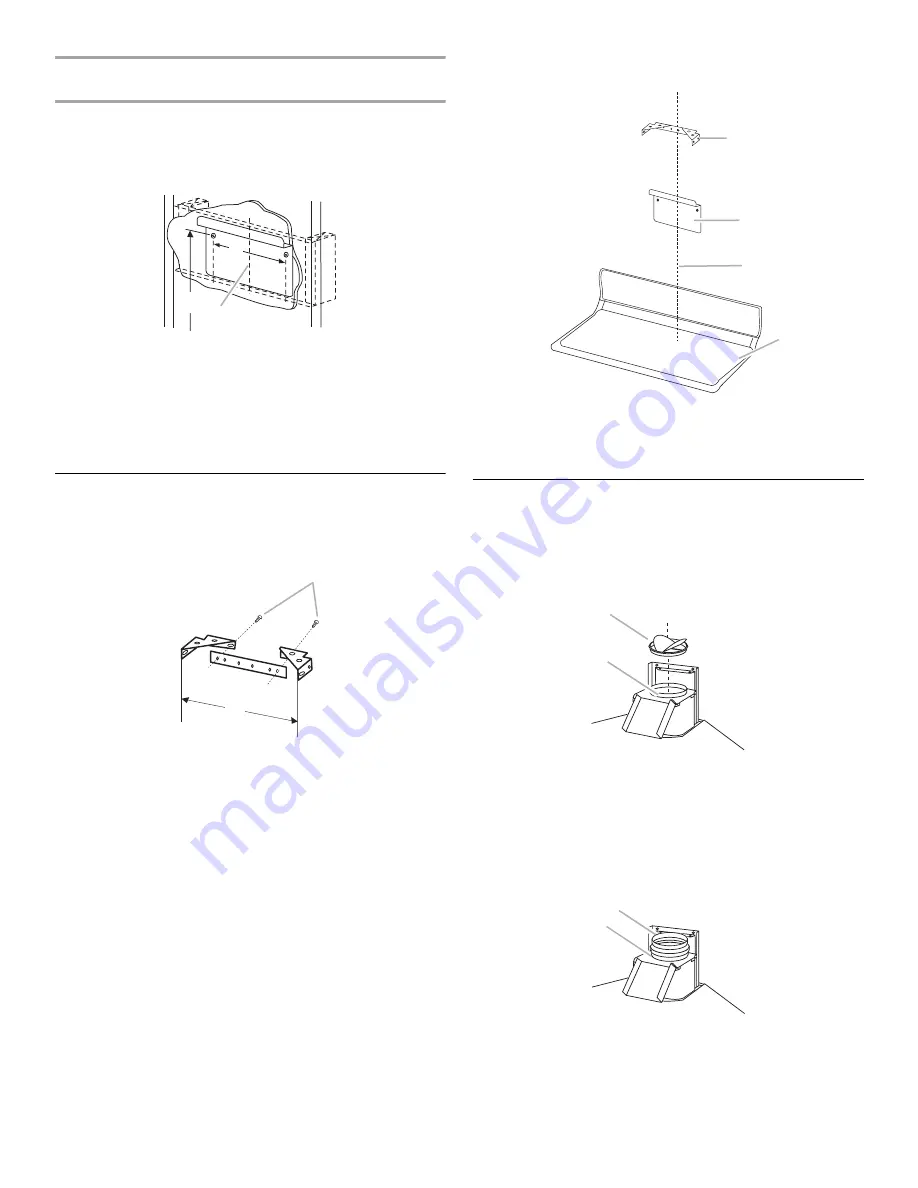
Wood Frame Installation - Style 2
(optional before drywall installation)

1.

Construct wood wall framing so that it is flush with interior 
surface of wall studs. The framing must be centered over the 
installation location. The height of the framing must allow for 
the mounting bracket to be secured to the framing within the 
dimensions shown.  

2.

After the wall surface is finished, drill two 

⁵⁄₃₂

" (4 mm) pilot 

holes.

3.

Install the mounting bracket to the frame using 
two 4.8 x 38 mm pan head mounting screws.

Install Flue Mounting Bracket

1.

Assemble the flue mounting bracket by attaching the 2 side 
brackets to the center bracket using the 2 flat head bracket 
screws provided. Adjust outside width as shown.

2.

Center the mounting bracket directly over the range hood 
location.

3.

Drill two 

⁵⁄₁₆

" pilot holes for drywall anchors.

4.

Install drywall anchors.

5.

Attach the flue mounting bracket to the ceiling using 
two 4.8 x 38 mm pan head mounting screws.

Prepare Range Hood

NOTE:

 Remove the plastic film from all exterior surfaces of the 

hood and decorative flues, prior to final installation.

Vented Installation

Install the damper into the duct connector of the range hood.

Non-vented (recirculating) Installation

Damper supplied with hood is not required in a non-vented 
(recirculating) installation. Install the 5" (12.7 cm) to 6" (15.2 cm) 
adapter supplied with the Charcoal Filter Kit, Part Number 
8212566. See “Assistance or Service” section to order.

A. 5

¹⁄₁₆

" (12.9 cm)

B. 38

¹⁄₁₆

" to 44

¹⁄₁₆

" (96.7 cm to 111.9 cm) above cooktop

C. Centerline

A. 3.9 x 5.7 mm flat head bracket screws
B. 9

¹³⁄₁₆

" (24.9 cm)

A

B

C

A

B

A. Flue mounting bracket
B. Hood mounting bracket

C. Centerline
D. Cooktop surface

A. Damper
B. Duct connector

A. 5" (12.7 cm) to 6" (15.2 cm) adapter
B. Blower collar

A

B

C

D

B

A

B

A

Summary of Contents for GZ9736XSS

Page 1: ...IÈRE POUR MONTAGE MURAL 30 76 2 CM ET 36 91 4 CM Instructionsd installationetGuided utilisationetd entretien Table of Contents Table des matières 2 IMPORTANT READ AND SAVE THESE INSTRUCTIONS FOR RESIDENTIAL USE ONLY IMPORTANT LIRE ET CONSERVER CES INSTRUCTIONS POUR UTILISATION RÉSIDENTIELLE UNIQUEMENT W10029770A ...

Page 2: ...ache conduit 23 Préparation de la hotte de cuisinière 23 Installation de la hotte de cuisinière 24 Achever l installation 27 UTILISATION DE LA HOTTE DE CUISINIÈRE 28 Commandes de la hotte de cuisinière 28 ENTRETIEN DE LA HOTTE DE CUISINIÈRE 28 Nettoyage 28 SCHÉMA DE CÂBLAGE 30 ASSISTANCE OU SERVICE 31 Liste d accessoires 31 Au Canada 31 GARANTIE 32 RANGE HOOD SAFETY You can be killed or seriously ...

Page 3: ...and to properly exhaust air be sure to duct air outside do not vent exhaust air into spaces within walls or ceilings attics or into crawl spaces or garages WARNING TO REDUCE THE RISK OF FIRE USE ONLY METAL DUCTWORK WARNING TO REDUCE THE RISK OF A RANGE TOP GREASE FIRE Never leave surface units unattended at high settings Boilovers cause smoking and greasy spillovers that may ignite Heat oils slowl...

Page 4: ... the model serial rating plate The model serial rating plate is located behind the left filter on the rear wall of the vent hood Canopy hood location should be away from strong draft areas such as windows doors and strong heating vents Cabinet opening dimensions that are shown must be used Given dimensions provide minimum clearance Consult the cooktop range manufacturer installation instructions b...

Page 5: ... damper do not use the damper supplied with the range hood Use caulking to seal exterior wall or roof opening around the cap The size of the vent should be uniform Cold weather installations An additional back draft damper should be installed to minimize backward cold air flow and a nonmetallic thermal break should be installed to minimize conduction of outside temperatures as part of the vent sys...

Page 6: ...ime delay fuse or circuit breaker is recommended It is recommended that a separate circuit serving only this appliance be provided Set the grounded 3 prong outlet within the space covered by the decorative flues Roof Venting Wall Venting Non vented recirculating A Roof cap B 6 15 2 cm round vent A Wall cap B 6 15 2 cm round vent A Deflector B 6 15 2 cm round vent Vent Piece 6 15 2 cm Round 45 elbo...

Page 7: ... and a suggested maximum of 30 76 2 cm for vented installations For non vented recirculating installations the minimum is 24 61 cm and the suggested maximum is 28 71 1 cm On 9 ft 2 7 m ceilings the required hood distance above the cooktop is a minimum of 26 66 cm and a suggested maximum of 30 76 2 cm The air vents on the upper decorative flue will be exposed after installation For ceilings from 9 ...

Page 8: ...on 3 Drill two pilot holes for drywall anchors 4 Install drywall anchors 5 Attach the flue mounting bracket to the ceiling using two 4 8 x 38 mm pan head mounting screws PrepareRangeHood NOTE Remove the plastic film from all exterior surfaces of the hood and decorative flues prior to final installation Vented Installation Install the damper into the duct connector of the range hood Non vented reci...

Page 9: ...anchors 8 Lift range hood back into the prepared installation location 9 Secure the range hood with four 4 8 x 38 mm pan head mounting screws 10 Mount the wiring assembly to the range hood with two 3 9 x 9 5 mm pan head screws Vented Installation Style 1 1 Attach an adequate length of 6 15 2 cm round metal duct to the range hood duct connector 2 Seal connection with vent clamp A 3 9 x 9 5 mm pan h...

Page 10: ...two 3 9 x 9 5 mm mounting screws 8 Install metal grease filters by inserting the back edge of filter into the rear channel of the filter opening Push handle toward the rear and push the filter up Push filter toward the front and insert into the front channel A Lower decorative flue B Recessed area A Upper decorative flue B Lower decorative flue C Upper decorative flue vents concealed A Upper decor...

Page 11: ... must be visible 7 Secure the deflector to the upper decorative flue with 4 flat head screws included in charcoal filter kit 8 Plug into a grounded 3 prong outlet 9 Raise the upper decorative flue until the holes align with the holes in the flue mounting bracket 10 Mount the decorative flue to the flue mounting bracket with two 3 9 x 9 5 mm mounting screws A Deflector B Adapter C Distance from ada...

Page 12: ...the light switch to the 1 position to turn on the light 2 Move the light switch to the 0 position to turn off the light Operating the blower and adjusting blower speed 1 Move the blower switch to the 1 position for low speed the 2 position for medium speed or the 3 position for high speed 2 Move the blower switch to the 0 position to turn off the blower Heat Sensing This range hood is equipped wit...

Page 13: ...sing a tissue to handle bulb or while wearing cotton gloves Do not touch bulb with bare fingers If new lights do not operate make sure the lamps are inserted correctly before calling service 1 Disconnect power or unplug the range hood 2 Use a flat blade screwdriver and gently pry the light cover loose 3 Remove the burned out lamp 4 Replace lamp with a 12 volt 20 watt maximum halogen lamp made for ...

Page 14: ...B OFF ON 2 4 4 6 1 3 3 5 BLK WHT WHT RED BLK ORG BLK RED BLK ORG WHT RED BLU BRN BLK ORG WHT RED BLU BRN M TRANSFORMER 12 V 120 V BLK WHT BLK WHT ORG WHT ORG RED WHT BLK CN1 CN4 CN3 CN2 YEL GRN YEL GRN YEL GRN WIRING BOX L N SE1L7A BLU BRN Motor Speed Measure between RED wire and Resistance Ohms 1 2 3 Black Orange White 22 27 32 LIGHTS BLK WHT YEL GRN BLK WHT ...

Page 15: ...ide after warranty service anywhere in the United States To locate the Whirlpool designated service company in your area you can also look in your telephone directory Yellow Pages For further assistance If you need further assistance you can write to Whirlpool Corporation with any questions or concerns at Whirlpool Brand Home Appliances Customer eXperience Center 553 Benson Road Benton Harbor MI 4...

Page 16: ... appliance is used in a country other than the country in which it was purchased DISCLAIMER OF IMPLIED WARRANTIES LIMITATION OF REMEDIES CUSTOMER S SOLE AND EXCLUSIVE REMEDY UNDER THIS LIMITED WARRANTY SHALL BE PRODUCT REPAIR AS PROVIDED HEREIN IMPLIED WARRANTIES INCLUDING WARRANTIES OF MERCHANTABILITY OR FITNESS FOR A PARTICULAR PURPOSE ARE LIMITED TO ONE YEAR OR THE SHORTEST PERIOD ALLOWED BY LA...

Page 17: ...as de non respect des instructions Votre sécurité et celle des autres est très importante Nous donnons de nombreux messages de sécurité importants dans ce manuel et sur votre appareil ménager Assurez vous de toujours lire tous les messages de sécurité et de vous y conformer AVERTISSEMENT DANGER Voici le symbole d alerte de sécurité Ce symbole d alerte de sécurité vous signale les dangers potentiel...

Page 18: ... extérieur ne pas décharger l air aspiré dans un espace vide du bâtiment comme une cavité murale un plafond un grenier un vide sanitaire ou un garage AVERTISSEMENT POUR RÉDUIRE LE RISQUE D INCENDIE UTILISER UNIQUEMENT DES CONDUITS MÉTALLIQUES AVERTISSEMENT POUR MINIMISER LE RISQUE D UN FEU DE GRAISSE SUR LA CUISINIÈRE Ne jamais laisser un élément de surface fonctionner à puissance de chauffage max...

Page 19: ...que signalétique de l appareil La plaque signalétique de l appareil est située derrière le filtre de gauche sur la paroi arrière de la hotte On doit toujours installer la hotte à distance des sources de courant d air fenêtres portes et bouches de chauffage Respecter les dimensions indiquées pour les ouvertures à découper dans les placards ces dimensions tiennent compte des valeurs minimales des dé...

Page 20: ... froid ainsi qu un élément d isolation thermique non métallique pour minimiser le transfert de chaleur par conduction vers l extérieur Le clapet anti reflux doit être placé du côté air froid par rapport à l élément d isolation thermique L élément d isolation thermique doit être aussi proche que possible de l endroit où le système d évacuation s introduit dans la partie chauffée de la maison Air d ...

Page 21: ...e décharge sur toit B Conduit dia 6 15 2 cm A Bouche de décharge murale B Conduit dia 6 15 2 cm A Déflecteur B Conduit dia 6 15 2 cm Composant Conduit de diamètre 6 15 2 cm coude à 45 2 5 pi 0 8 m coude à 90 5 pi 1 5 m A A B B B A 1 coude à 90 5 pi 1 5 m 1 bouche de décharge murale 0 pi 0 m section droite de 8 pi 2 4 m 8 pi 2 4 m Longueur du système 13 pi 3 9 m Coude à 90 6 pi 1 8 m 2 pi 0 6 m Bou...

Page 22: ...istance maximale suggérée est 30 76 2 cm pour une installation avec décharge à l extérieur Pour une installation sans décharge à l extérieur recyclage la distance de séparation minimale est 24 61 cm et la distance maximale suggérée est 28 71 1 cm Dans le cas d un plafond de 9 pi 2 7 m la distance de séparation minimale exigée entre la hotte et la table de cuisson est 26 66 cm la distance maximale ...

Page 23: ...les d ancrage 4 Installer les chevilles d ancrage 5 Fixer la bride de montage du cache conduit sur le plafond utiliser deux vis de 4 8 x 38 mm tête bombée Préparationdelahottedecuisinière REMARQUE Enlever le film de plastique des surfaces extérieures de la hotte et des sections du conduit décoratif avant l installation finale Installation avec décharge à l extérieur Installer le clapet anti reflux...

Page 24: ...n panneau de gypse insérer les chevilles d ancrage 8 Soulever la hotte de cuisinière pour la placer de nouveau à l emplacement d installation préparé 9 Fixer la hotte de cuisinière avec quatre vis de montage à tête bombée de 4 8 x 38 mm 10 Fixer le module de câblage sur la hotte de cuisinière avec deux vis de 3 9 x 9 5 mm tête bombée Installation avec décharge à l extérieur Style 1 1 Raccorder sur...

Page 25: ...les reliée à la terre 6 Soulever la section supérieure du cache conduit décoratif pour aligner les trous avec les trous de la bride de montage du cache conduit A Conduit métallique rond de diamètre 6 15 2 cm B Bride de conduit A Cache conduit décoratif section inférieure B Zone d insertion A Cache conduit décoratif section supérieure B Cache conduit décoratif section inférieure C Cache conduit déc...

Page 26: ... raccord d adaptation de 5 12 7 cm Assurer l étanchéité de la jointure avec une bride de conduit 3 Raccorder le déflecteur sur le conduit métallique flexible 4 Fixer le conduit sur le raccord du déflecteur utiliser des brides de conduit 5 Faire glisser la section inférieure du cache conduit décoratif dans la zone d insertion sur le sommet de la hotte d extraction 6 Faire glisser la section supérie...

Page 27: ...rage à la position 1 La lampe devrait s allumer 2 Pousser le commutateur du ventilateur à la position 1 Le ventilateur devrait fonctionner 3 Placer le commutateur de vitesse du ventilateur à la position 1 pour la vitesse minimale à la position 2 pour la vitesse moyenne ou à la position 3 pour la vitesse maximale 4 Pour commander l arrêt du ventilateur et l extinction des lampes placer les commutat...

Page 28: ...sse s il détecte une chaleur excessive au dessus de la surface de cuisson Si le ventilateur est éteint le thermostat de détection de chaleur le mettra en marche à vitesse élevée Si le ventilateur fonctionne à basse vitesse le thermostat de détection de chaleur commande le passage à une vitesse élevée Lorsque la température atteint un niveau normal le ventilateur revient à son réglage initial ENTRE...

Page 29: ... les doigts nus Si les nouvelles lampes ne fonctionnent pas vérifier que chaque lampe est correctement insérée dans sa douille avant de faire un appel de service 1 Déconnecter la source de courant électrique ou débrancher la hotte 2 À l aide d un tournevis à lame plate dégager doucement le couvercle de lampe 3 Enlever l ampoule grillée 4 Installer une lampe à halogène de 12 V maximum 20 watts avec...

Page 30: ...CUITS ALLUMAGE ARRÊT MARCHE 2 4 4 6 1 3 3 5 N BL BL R N ORANGE N R N ORANGE BL R BU MAR N ORANGE BL R BU MAR M TRANSFORMATEUR 12 V 120 V N BL N BL ORANGE BL ORANGE R BL N CN1 CN4 CN3 CN2 JA VE YEL GRN JA VE BOÎTIER DE RACCORDEMENT L N SE1L7A BU MAR Vitesse du moteur Mesure entre conducteur ROUGE et Résistance Ohms 1 2 3 Noir Orange Blanc 22 27 32 LAMPES N BL JA VE N BL ...

Page 31: ...n Pièce numéro 8212566 AuCanada Veuillez appeler sans frais le Centre d interaction avec la clientèle de Whirlpool Canada LP au 1 800 807 6777 Nos consultants vous renseigneront sur les sujets suivants Caractéristiques et spécifications sur toute notre gamme d appareils électroménagers Consignes d utilisation et d entretien Ventes d accessoires et pièces de rechange Références aux marchands locaux...

Page 32: ...é CLAUSE D EXONÉRATION DE RESPONSABILITÉ AU TITRE DES GARANTIES IMPLICITES LIMITATION DES RECOURS LE SEUL ET EXCLUSIF RECOURS DU CLIENT DANS LE CADRE DE LA PRÉSENTE GARANTIE LIMITÉE CONSISTE EN LA RÉPARATION PRÉVUE CI DESSUS LES GARANTIES IMPLICITES Y COMPRIS LES GARANTIES APPLICABLES DE QUALITÉ MARCHANDE ET D APTITUDE À UN USAGE PARTICULIER SONT LIMITÉES À UN AN OU À LA PLUS COURTE PÉRIODE AUTORI...

Reviews: