background image

ICE CUBES MAKERS Range

SPRAY Technology

Summary of Contents for ICE CUBES MAKERS Series

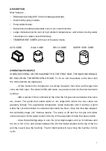
Page 1: ...ICE CUBES MAKERS Range SPRAY Technology ...

Page 2: ...stallation Required conditions for placement of unit Water and drainage 17 Connection to water mains water condensing Connection to drain Electrical connection 18 Starting Preliminary checking 19 Starting 20 Adjustments Fan pressostat air condensing 21 Security pressostat 22 Maintenance and cleaning instructions and procedures Maintenance chart 23 Water condenser Air condenser Evaporator Water tra...

Page 3: ...than producing ice cubes with drinking water It is extremelly dangerous to modify or try to modify this appliance Besides it would automatically cancel the warranty totally This appliance is not intended for use including children with reduced physical sensory or mental capabilities or lack of experience and knowledge unless they have been given supervision or instruction concerning use of the app...

Page 4: ...vere damage to the unit In case of breakdown contact an authorised distributor We strongly recommend using only original replacement parts Waste and other material should be disposed in accordance to local regulations and procedures for waste disposal CLEANING AND MAINTENANCE OPERATIONS ARE NOT COVERED BY THE WARRANTY AND WILL BE INVOICED BY THE INSTALLER ...

Page 5: ...lve are both open The water bin fills with water any excess is lost via the maximum level overflow After a period of time controlled by the timer the hot gas valve and water inlet valve are closed The pump then sends water to the evaporator where the ices cubes are gradually formed The evaporation temperature slowly descends until it reaches a point where the cycle thermostat is connected and star...

Page 6: ...wire goes to 2 on terminal G1 which at this moment is connecting 1 and 4 A red wire connects bin thermostat T1 and micros G1 and G2 which close the circuit with 4 and provide current via G1 to the timer G At this point the following are connected v COMPRESSOR S v WATER INLET VALVE P v HOT GAS VALVE Q v TIMER MOTOR G Since the motor of the timer G is working during 1 3 minutes the roler of micro of...

Page 7: ...ve The combined effect of hot gas and water sprayed on the top of the evaporator will release the ice cubes and change the position of the cycle thermostat T2 The ice production and defrosting cycle will continue until the ice storage bin is full at which point cycle thermostat T1 will disconnect the machine but never during a cycle but at the beginning of the defrosting stage since during the pro...

Page 8: ...8 ...

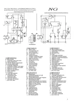
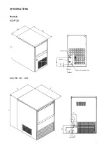
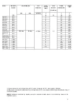
Page 9: ...9 SPECIFICATIONS Models NDP 20 NG DP 30 150 ...

Page 10: ...NG DP 45 A 18 8 18 8 45 465x595x795 525x645x920 53 NG DP 45 W 24 18 8 42 8 45 465x595x795 525x645x920 53 NG DP 60 A 28 8 28 8 48 535x595x795 595x645x920 67 0 40 NG DP 60 W 30 28 8 58 8 48 535x595x795 595x645x920 67 0 40 NG DP 80 A 14 6 10 6 58 715x595x945 780x670x1055 78 0 57 NG DP 80 W 54 14 6 68 6 58 715x595x945 780x670x1055 78 0 57 NG DP 110 A 17 2 17 2 89 715x700x1050 780x780x1070 100 NG DP 11...

Page 11: ...ITY COMPRESSOR MODEL HIGH PRESSURE TOTAL INTENST AMPS TO INSTALL POWER ABS MIN MAX AVERAGE 2 1 2 GR A A W W NDP 20 A 345 2 1 5 355 NDP 20 W 285 2 1 5 355 NG 30 A 320 2 1 4 423 NG 30 W 300 2 1 4 423 NG 35 A 360 2 1 4 540 NG 35 W 310 2 1 4 540 NG 45 A 420 3 3 8 550 NG 45 W 365 3 3 8 550 NG DP 60 A 420 15 5 bar 18 bar 2 5 bar 3 5 10 3 8 650 NG DP 60 W 350 3 5 3 8 650 NG DP 80 A 470 3 1 2 780 NG DP 80...

Page 12: ... 25 25 20 19 21 24 25 27 28 28 28 15 22 24 27 28 30 20 31 31 10 24 27 29 31 32 33 33 33 5 26 29 31 33 34 35 35 35 NG 30 Tw Tr 45 40 35 30 25 20 15 10 35 12 16 19 22 24 25 26 26 30 18 22 25 28 30 31 32 32 25 23 28 31 34 36 37 38 37 20 28 32 36 38 40 42 42 42 15 33 37 40 43 45 30 47 47 10 36 40 44 46 48 50 50 50 5 39 6 43 47 49 51 53 53 53 ...

Page 13: ...10 42 47 51 54 56 58 59 59 5 46 51 54 58 60 61 62 62 NG 45 Tw Tr 45 40 35 30 25 20 15 10 35 18 3 24 4 29 5 33 5 36 5 38 5 39 4 39 4 30 27 5 33 6 38 7 42 8 45 8 47 7 48 7 48 6 25 35 8 41 9 47 51 1 54 1 56 57 56 9 20 43 2 49 3 54 3 58 4 61 4 63 4 64 3 64 2 15 49 5 55 7 60 7 64 8 67 8 45 70 7 70 6 10 55 61 1 66 1 70 2 73 2 75 2 76 1 76 5 59 4 65 5 70 6 74 6 77 7 79 6 80 6 80 5 ...

Page 14: ... 5 85 8 85 6 15 66 1 74 2 81 86 4 90 4 60 94 3 94 2 10 73 3 81 4 88 2 93 6 97 6 100 2 101 5 101 4 5 79 2 87 4 94 1 99 5 103 5 106 2 107 4 107 3 NG 80 Tw Tr 45 40 35 30 25 20 15 10 35 32 43 52 59 64 68 70 70 30 49 59 68 76 81 84 86 86 25 63 74 83 90 96 99 101 101 20 76 87 96 103 109 112 114 114 15 88 98 108 115 120 80 125 125 10 97 108 117 124 130 133 135 135 5 105 116 125 132 138 141 143 143 ...

Page 15: ...1 214 214 15 165 185 202 215 225 150 235 235 10 183 203 220 233 244 250 253 253 5 198 218 235 248 258 265 268 268 Tw Tr 45 40 35 30 25 20 15 10 35 44 59 72 81 89 94 96 96 30 67 82 94 104 111 116 119 118 25 87 102 114 124 132 137 139 139 20 105 120 132 142 150 154 157 157 15 121 136 148 158 165 110 172 172 10 134 149 161 171 178 183 186 185 5 145 160 172 182 189 194 197 196 ...

Page 16: ...Disposal ITV Be sure to include model name and serial number on all claims Serial number is located in the following three places Packing There is a label stick onto the cardboard packing bearing this serial number 1 Machine body On the back of the machine 1 Rating plate and serial number WARNING DO NOT LEAVE PACKING MATERIALS PLASTIC BAGS CARDBOARD Located at the back of the machine 1 Water coole...

Page 17: ...17 BOXES ETC IN REACH OF CHILDREN ...

Page 18: ...in the front part of the machine The machines will work properly even if they are located in places with little ventilation at the rear and lateral sides The air is expelled by the front grill Bear in mind the previous remarks if the premises where the machine is located is very dusty or smoky The floor on which the machine will be place should be solid and as leveled as possible Water and drainag...

Page 19: ...ure Water pressure should be between 0 7 and 6 Bars 10 85 psi If water pressure excedes these values installation of appropriate corrective units will be necessary It is important that water tubing does not come close to or in contact with any heat sources or heat generated by unit as this could decrease production Connecting Unit To Drain Drain must be located at least 150mm below machine Drain t...

Page 20: ...ry Check a Is machine levelled b Are voltage and frequency of mains supply the same as indicated on rating plate c Is drainage system functioning d Is air circulation and room temperature adequate Air cooled models TEMPERATURE ROOM WATER MAXIMUM 43 C 35ºC MINIMUM 5º C 5ºC a Is water pressure adequate MINIMUM 0 7 Bar MAXIMUM 6 Bar NOTE To install a pressure reducer If water inlet pressure is more t...

Page 21: ... the machine 4 Ensure that there are no strange vibrations or scraping sounds 5 Check that the water curtain moves freely 6 Verify that the nozzles send water to the evaporator in the correct direction uniform fans 7 After 10 minutes check that the water bin has no leaks on the maximum level overflow ATTENTION ADVISE THE FINAL USER ON MAINTENANCE PROCEDURES WHICH ARE NOT INCLUDED IN WARRANTY AS WE...

Page 22: ...tion are both reduced Pressure can be increased by turning the small screw on the pressostat clockwise A full turn is equivalent to about 1 5 Bar Fan pressostat air condensation Pressure Control operates on high pressure by starting and stopping fan Differential is a fixed 1 Bar or 14 psi Cut off pressure must be 15 Bar 214 psi Low pressure values may cause difficulties during harvest cycle Higher...

Page 23: ...ed the limit when a Air circulation is not sufficient room temperature is too high or condenser is dirty air cooled models b There is not enough water in the system o temperature is too high in water cooled models HIGH PRESSURE REGULATION fixed 3030 22 Bar from model 110 part 2683 27 21 Bar 380 296 psi ...

Page 24: ...s MAINTENANCE TABLE PROCEDURE MONTHLY QUARTERLY BIANNUAL ANNUAL BIENNIAL DURANTION Air condenser cleaning 0000 0000 30 minutes Water condenser cleaning 90 minutes Inyectors cleaning 30 minutes Fabrication head filter cleaning 30 minutes Water circuit cleaning 45 minutes Sanitary cleaning 30 minutes Water filter cleaning replacement 30 minutes Stock deposit cleaning Unit cleaning 0000 Depending on ...

Page 25: ...cover 3 Place the overflow pipe Remove the evaporator cover 4 Prepare a solution of 50 phosphoric acid in distilled water Do not use hydrochlorate acid Pour slowly this solution in the upper part of the evaporator until it overflows in the water tray The mixture is more effective with the water between 35ºC and 40ºC 5 Let solution stand for 10 minutes 6 Remove the overflow pipe and wait until the ...

Page 26: ...T THE FORMED WATER FANS ARE UNIFORM AND ALL EQUAL If necessary disassemble clean and put again in the right position Cleaning the ice bin 1 Unplug the machine turn off water supply and empty storage bin of ice 2 Wipe with a kitchen cloth soaked in lye and detergent 3 If white lime stains do not vanish rub with some lemon or vinegar wait for a few minutes and wipe with the cloth again Rinse with pl...

Page 27: ...tenance is carried out on the machine check all water connexions braces tubes and hoses in order to eliminate leaks and prevent breakages and flooding SPECIAL ADVICE CONCERNING R 404 REFRIGERANT R 404 is a mixture of 3 liquid phase gases On evaporating the 3 component gases separate Always use the liquid phase valve at the end of condenser or accumulator for refills and purges When replacing a com...

Page 28: ...ust presostat G Water presostat valve faulty or wrongly adjusted G Replace or adjust H Cooling water pressostat is faulty or badly adjusted H Adjust or change 3 All the electrics work but the compressor klixons J Non condensable gases in system J Purge system A Unprimed pump A Check overflow water bin for leaks water entry valve and prime the pump B Faulty pump B Replace C Water does not enter int...

Page 29: ...faulty inlet cooling water valve D Check fan and re adjust pressostat or replace E Refrigerant charge too high or too low E Adjust F Faulty water inlet valve leaks and does not close fully F Check and replace 6 Low ice production G Inefficient compressor G Replace A Start of cycle thermostat adjusted too low or faulty A Adjust and or replace B Timer wheels do not run B Tighten screws on timer C Fa...

Reviews: