FOR SERVICE TECHNICIAN ONLY - DO NOT REMOVE OR DESTROY
POUR LE TECHNICIEN SEULEMENT - NE PAS ENLEVER NI DÉTRUIRE
PART NO. 3957668
PAGE 14
PIÈCE N
o
3957668
b)
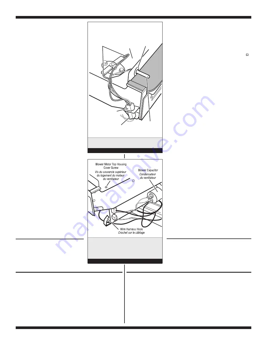
Remove the wires from the hook in
the blower motor housing. See
figure 14.
c)
Pull the blower motor housing
assembly far enough forward so you
can access the lint drawer switch.
See figure 12.
d) IMPORTANT:
Discharge the blower
capacitor by touching a 20,000
Ω
resistor to the terminals and chassis.
See figure 14.
e)
Remove the blower motor top
housing cover screws and position
the assembly out of the way.
f)
Disconnect the two yellow wires from
the lint drawer switch terminals.
g)
Bend the three lint drawer switch's
metal tabs straight out.
h)
Release the bottom and top locking
tabs on the switch and push it out of
its housing cutout.
8.
To remove the blower motor:
a)
Remove the blower motor housing
assembly and the top housing cover
by following steps 7a through 7e.
b)
Remove the four 7mm (3/8") nuts,
split washers, and flat washers from
the top blower motor housing. Lift
the top housing off the motor, and
position it to the left side.
c)
Release and disconnect the
following connectors:
✔
2 blower motor harness
connectors
✔
2 blower motor harness plugs
from the mounting bracket
✔
3 blower capacitor wires
d)
Turn the blower motor assembly
over, and position it so that you can
access the bottom screws.
e)
Remove the four 7mm (3/8") motor
mounting plate nuts, and the five
motor mounting screws from the
blower motor assembly.
f)
Remove the mounting plate and pull
the motor wiring through the opening.
g)
Lift the motor and fan from the
housing.
REMOVING THE TOE
PANEL
1.
Remove four screws from the top of the
toe panel.
2.
Slide the toe panel down, then pull it out
from the bottom.
b)
Dégager les conducteurs du crochet (sur le
logement du moteur du ventilateur). Voir
figure 14.
c)
Tirer le logement du moteur du ventilateur
suffisamment vers l’avant pour pouvoir accéder
au contacteur du tiroir à charpie. Voir figure 12.
d) IMPORTANT :
Décharger le condensateur du
ventilateur : placer une résistance de 20 000
en contact entre les bornes et le châssis. Voir
figure 14.
e)
Ôter les vis du couvercle du logement du
moteur du ventilateur et écarter l’ensemble.
f)
Débrancher les deux conducteurs jaunes des
broches du contacteur du tiroir à charpie.
g)
Redresser les trois pattes métalliques du
contacteur du tiroir à charpie.
h)
Dégager les pattes de blocage supérieure et
inférieure sur le contacteur, et extraire le
contacteur à travers l’ouverture dans le
logement.
8.
Dépose du moteur du ventilateur :
a)
Enlever le logement du moteur du ventilateur, et
le couvercle du logement : exécuter les étapes
7a à 7e.
b)
Ôter les quatre écrous de 7 mm (3/8 po), les
rondelles freins, et les rondelles plates du
logement du moteur du ventilateur. Séparer le
couvercle supérieur du logement du moteur;
placer celui-ci à gauche.
c)
Détacher/débrancher les connecteurs suivants :
✔
2 connecteurs de câblage du moteur du
ventilateur
✔
2 fiches du câblage du moteur du ventilateur
sur la bride de montage
✔
3 conducteurs du condensateur du ventilateur
d)
Retourner le moteur du ventilateur; positionner
celui-ci de manière à pouvoir accéder aux vis
inférieures.
e)
Ôter les quatre écrous de 7 mm (3/8 po) de la
plaque de montage du ventilateur, et les cinq vis
de montage du moteur du ventilateur.
f)
Ôter la plaque de montage et extraire le câblage
du moteur à travers l’ouverture.
g)
Soulever le moteur et le ventilateur pour les
séparer du carter.
Temperature
Sensor Connector
Harness Connector
Termperature
Sensor Clip
Capteur
thermométrique
Termperature Sensor
Blower Motor Top
Housing Cover
Exhaust High
Limit Wires
Connecteur - câblage
Clip du capteur
thermométrique
Conducteurs
des décharge –
limite haute
Connecteur - capteur
thermométrique
Couvercle supérieur
du logement
du moteur
du ventilateur
Temperature sensor
connections.
Connexions du capteur
thermométrique.
Figure 13
Discharge the blower
capacitor at right
side of blower
motor housing.
Décharger le
condensateur du
ventilateur sur le côté
droit du logement du
moteur du ventilateur.
Figure 14
DÉPOSE DU PANNEAU DE
PLINTHE
1.
Ôter les quatre vis au sommet du panneau de
plinthe.
2.
Faire glisser le panneau de plinthe vers le bas puis
le retirer.
REMOVING THE BACK PANEL
1.
Unplug dryer or disconnect power.
2.
Remove the top panel.
3.
Remove the three screws from each side of the back panel.
4.
Remove three screws from around the exhaust vent, one from
the top, and one on each side.
5.
Remove the five screws that are around the power cord access.
NOTE:
There are 14 screws total for the back panel, not including
the top panel screws.
DÉPOSE DU PANNEAU ARRIÈRE
1.
Débrancher la sécheuse ou déconnecter la source de courant électrique.
2.
Enlever le panneau supérieur.
2.
Ôter les trois vis de chaque côté du panneau arrière.
3.
Ôter les trois vis autour de la bouche de sortie - une vis au sommet, et une vis
de chaque côté.
4.
Ôter les cinq vis autour du point d’accès du cordon d’alimentation.
NOTE :
Il y a un total de 14 vis pour le panneau arrière (ceci n’inclut pas les vis
du panneau supérieur).


