background image

v

Turntable Motor ................................................................................................................. 5-3
Humidity Sensor ............................................................................................................... 5-4
Hood Exhaust Fan Motor .................................................................................................. 5-4
AC Line Filter .................................................................................................................... 5-5
Thermostats ...................................................................................................................... 5-5

DIAGNOSIS & TROUBLESHOOTING ..................................................................................... 6-1

Interlock Switch Checkout Procedures ............................................................................. 6-1
Touch Panel and Electronic Control Test .......................................................................... 6-2
Microwave Oven Power Output Test ................................................................................ 6-3
Failure Codes Indications ................................................................................................. 6-3

WIRING DIAGRAm & STRIP CIRCUITS .................................................................................. 7-1

Wiring Diagram - 8205889 - Sensor Model ...................................................................... 7-1
Wiring Diagram - 8205660 - Non Sensor Model ............................................................... 7-2
Strip Circuits ..................................................................................................................... 7-3

Microwave Cooking ..................................................................................................... 7-3
Hood Exhaust Fan On High Automatically .................................................................. 7-3
Hood Exhaust Fan On Low Speed.............................................................................. 7-3
Hood Exhaust Fan On High / Medium ........................................................................ 7-4
Microwave Oven Plugged In—Time of Day Displayed ............................................... 7-4
Door Open—Oven Cavity Light Is On ......................................................................... 7-4
Cooktop Light On High ................................................................................................ 7-4
Cooktop Light On Low (Night Light) ............................................................................ 7-4

TABLE OF CONTENTS - CONTINUED

Summary of Contents for KM-30 8178573

Page 1: ... MICROWAVE OVEN HOOD COMBINATION KM 30 8178573 ...

Page 2: ...use the Wiring Diagram supplied with the product when servicing the unit GOALS AND OBJECTIVES The goal of this Job Aid is to provide detailed information that will enable the In Home Service Profes sional to properly diagnose malfunctions and repair the Microwave Oven Hood Combination The objectives of this Job Aid are to Understand and follow proper safety precautions Successfully troubleshoot an...

Page 3: ...tions 4 1 Removing the Turntable Motor Hood Cooktop Lamp Assembly 4 2 Removing the Control Panel Control Board 4 4 Removing the Motor Capacitor and Line Fuse 4 6 Removing the Door Switches 4 6 Removing the Oven Cavity Lamp and Charcoal Filter 4 8 Removing the Oven Rack Retainers 4 9 Removing the Outer Cabinet 4 10 Removing the Thermostats and Thermistor 4 11 Removing the Magnetron 4 12 Removing th...

Page 4: ...s Indications 6 3 WIRING DIAGRAM STRIP CIRCUITS 7 1 Wiring Diagram 8205889 Sensor Model 7 1 Wiring Diagram 8205660 Non Sensor Model 7 2 Strip Circuits 7 3 Microwave Cooking 7 3 Hood Exhaust Fan On High Automatically 7 3 Hood Exhaust Fan On Low Speed 7 3 Hood Exhaust Fan On High Medium 7 4 Microwave Oven Plugged In Time of Day Displayed 7 4 Door Open Oven Cavity Light Is On 7 4 Cooktop Light On Hig...

Page 5: ...P 331 AOD It is neither necessary nor advisable to attempt measurement of high voltage Attaching the adaptor ground terminal to the wall receptacle cover screw does not ground the appliance unless the cover screw is metal and not insulated and the wall receptacle is grounded through the house wiring Electrostatic discharge esd sensitive electronic ESD problems are present everywhere ESD may damage...

Page 6: ...the magnetron Routine service safety procedures should be exercised at all times Untrained personnel should not attempt service without a thorough review of test procedures and safety information contained in this Job Aid Whirlpool microwave ovens have a monitoring system designed to ensure proper operation of the safety interlock systems The interlock monitor switch will immediately cause the ove...

Page 7: ...ping or abuse C Before turning on the microwave power for any service test or inspection within the microwave generating components check the magnetron wave guide or transmission line and cavity for proper alignment integrity and connections D Any defective or misadjusted components in the interlock monitor door seal and microwave generation and transmission systems shall be repaired replaced or a...

Page 8: ...lly register small emissions but they must be no greater than 4 mw cm2 to allow for measurement uncertainty NOTE Enter leakage readings in BEFORE and AFTER spaces on the service document All microwave ovens exceeding the emission level of 4 mw cm2 must be reported to Dept of Service for microwave ovens immediately and the owner should be told not to use the micro wave oven until it has been repair...

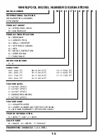
Page 9: ...FAN T TURNTABLE MODEL VARIATIONS 0 9 CUBIC FEET 04 4 CU FT 09 0 9 CU FT 15 1 5 CU FT 06 6 CU FT 10 1 0 CU FT 16 1 6 CU FT 07 7 CU FT 12 1 2 CU FT 17 1 7 CU FT 08 8 CU FT 14 1 4 CU FT FEATURE LEVEL 0 30 KIT IF KIT 2 22 KIT IF KIT 4 24 KIT IF KIT 5 SENSORED MODEL 7 27 KIT IF KIT FEATURE CODE C CSA APPROVED S CARRY IN WARRANTY EFFECTIVE 02 96 X IN HOME WARRANTY EFFECTIVE 02 96 YEAR OF INTRODUCTION S ...

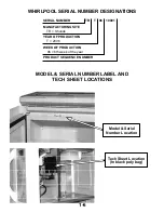
Page 10: ...R TR T 06 10001 MANUFACTURING SITE TR Shunde YEAR OF PRODUCTION T 2006 WEEK OF PRODUCTION 06 6th week of the year PRODUCT SEQUENCE NUMBER Model Serial Number Label and Tech Sheet Locations Model Serial Number Location Tech Sheet Location In black poly bag ...

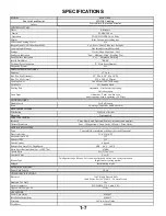
Page 11: ...erating 30 Watt DOOR FEATURES Handle Latch Yes Pull to open Seals Two Stage Capacitive and Reflective MICROWAVE SYSTEM Distribution Top Feed w Stirrer Magnetron One standard SAFETYFEATURES Interlock Three Door Latch Operated Primary secondary and monitor Thermal Protectors Four 1 Magnetron 1 Oven Cavity 1 Hood 1 Wave Guide VENTILATION SYSTEM Type Convertible Recirculation or Exhaust Vertical Horiz...

Page 12: ...tts DOOR FEATURES Seals Two Stage Capacitive and Reflective MICROWAVE SYSTEM Distribution Top Feed w o Stirrer Magnetron One standard SAFETY FEATURES Interlock Three Door Latch Operated Primary secondary and monitor Thermal Protectors Four 1 Magnetron 1 Oven Cavity 1 Hood 1 Wave Guide VENTILATION SYSTEM Type Convertible Recirculation or Exhaust Vertical Horizontal Duct Outlet Size 3 1 4 H x 10 W R...

Page 13: ...n is operating 30 Watts Two Stage Capacitive and Reflective Two Stage Capacitive and Reflective Top Feed w o Stirrer Top Feed w o Stirrer One standard One standard Three Door Latch Operated Primary secondary and monitor Three Door Latch Operated Primary secondary and monitor Primary secondary and monitor Primary secondary and monitor Four 1 Magnetron 1 Oven Cavity 1 Hood 1 Wave Guide Four 1 Magnet...

Page 14: ...LL BE PRODUCT REPAIR AS PROVIDED HEREIN IMPLIED WARRANTIES INCLUDING WARRANTIES OF MERCHANTABILITY OR FITNESS FOR A PARTICULAR PURPOSE ARE LIMITED TO ONE YEAR OR THE SHORTEST PERIOD ALLOWED BY LAW WHIRLPOOL SHALL NOT BE LIABLE FOR INCIDENTAL OR CONSEQUENTIAL DAMAGES SOME STATES AND PROVINCES DO NOT ALLOW THE EXCLUSION OR LIMITATION OF INCIDENTAL OR CONSEQUENTIAL DAMAGES OR LIMITATIONS ON THE DURAT...

Page 15: ...ds rear of unit Unplug wire turn fan motor over and plug wire back into the quick disconnect socket over the top of the fan motor Airflow towards top of unit TOP VENTED AIR REAR VENTED AIR RECIRCULATING AIR Airflow towards front of unit Note this is the way the unit is shipped ...

Page 16: ...2 2 NOTES ...

Page 17: ...rculates air within the unit to assist cooking performance and cool the operating compo nents This process is accomplished by using one side of the blower motor assembly to pull ambient air into the unit to cool the working components and the remaining side of the blower for exhaust ing steam and cooking odors Component cooling Cooktop Venting ...

Page 18: ...3 2 Air is circulated in the unit to assist cooking performance The motor operates at two speeds low speed all of the time and high speed during sensor cooking modes ...

Page 19: ...on thermostat opens at 257ºF 125ºC closes at 185ºF 85ºC G Cavity thermostat 1 opens at 257ºF 125ºC closes at 31ºF 35ºC H Cavity thermostat 2 opens at 257ºF 125ºC closes at 31ºF 35ºC I H V transformer J H V diode K NTC thermistor L Motor capacitor M Line fuse N Fuse holder O Power display P Electronic control Q Touch panel R Secondary interlock switch S Monitor interlock switch T Primary interlock ...

Page 20: ...r the top edge of the cover so you can access the component wiring below it 3 Disconnect the wire connector at the right side 4 Remove the wire from the wire clip towards the middle of the bottom cover 5 To remove the turntable motor a Remove the glass turntable roller assembly and spindle from inside the oven cavity b There are two small holes on the connector Lower the bottom cover just far enou...

Page 21: ...e right of the lamp housing that secure the lamp fixture electrical box cover to the inside of the bottom cover a c NOTE When reassembling the wire connec tor onto the turntable motor make sure the holes of the connector are facing away from the bottom of the unit outward toward you d Remove the bottom cover from the unit see page 4 2 steps 1 thru 4 e Remove the electrical box cover to expose the ...

Page 22: ...onnect power 2 Remove the two screws from the top of the grille 5 Push the panel up to release the tabs from the slots Pull the panel away from the microwave unit to gain access to the back side of it 3 Pull the top of the air grille forward lift the bot tom tabs from the slots and remove the grille 4 Remove the screw from the top of the control panel 6 Disconnect the seven wire connectors from th...

Page 23: ...ve 5 screws from the bottom board to release it from the touch panel assembly c Press in on the locking tab end of the arm and lift the arm to release the touch panel rib bon cable d You can now remove the microcomputer board assembly e To remove the microcomputer board mount ing bracket release 4 tabs f Pull the bracket out of the touch panel as sembly ...

Page 24: ...ew Line Fuse Motor Capacitor Screw 4 To remove the line fuse pull the fuse out of the fuse holder To remove the door switches 1 Unplug microwave oven or disconnect power 2 Remove the control panel see page 4 4 3 Open the microwave oven door 4 The Primary interlock switch and Monitor inter lock switch are attached to a mounting bracket at the top Top switch assembly screw 5 The secondary interlock ...

Page 25: ...ire connectors from the termi nals 9 To remove the monitor interlock switch from the mounting bracket press the locking tabs away from the switch and slide the switch up off the mounting posts Locking tab Locking tab 10 The Primary interlock switch and Monitor interlock switch are located on opposite sides of their mounting bracket The Primary inter lock switch can be removed from the mounting bra...

Page 26: ...ver to access the lamp Lift tab to access lamp To remove the charcoal filter 1 Unplug microwave oven or disconnect power 2 Remove the air grille see page 4 4 3 Lift the charcoal filter from the mounting frame and pull it out of the microwave unit 4 Replace the charcoal filter with the correct replacement filter 4 Unscrew the lamp from the socket There will be a dab of silicone that is intended to ...

Page 27: ...l parts Sharp edges may be present and you can cut yourself if you are not careful 1 Unplug microwave oven or disconnect power 2 Open the microwave oven door 3 Locate the four oven rack retainers two on each side of the oven interior 4 Remove the one screw that attaches each rack retainer to the wall of the microwave oven ...

Page 28: ...e on the top of the microwave unit 4 Remove the 1 screw visible on the side 5 Remove the 9 screws around the edge of the back panel 6 Remove the 3 screws on each end of the bot tom panel not shown 7 After removing all the screws pull each side out and push it back from the front corners of the unit to release the tabs on the inside front edge of the cabinet 8 The cabinet may now be completely remo...

Page 29: ... pacitor with a 20 000 Ohm resistor to chassis ground Cavity thermostat 1 Cavity thermostat 2 NTC thermistor Magnetron thermostat To remove the magnetron thermostat 1 Remove 2 screws and disconnect the wire connectors To remove the Cavity thermostats 1 Slide the thermostat up and out from behind the mounting bracket Remove the wire con nectors To remove the NTC thermistor base thermis tor 1 Remove...

Page 30: ...e 4 10 3 CAUTION Discharge the high voltage ca pacitor with a 20 000 Ohm resistor to chassis ground 4 Remove 3 screws that secure the air shroud and 1 screw that secures the ground wire Lift the air shroud up to expose two of the four screws that secure the magnetron to the unit 5 Remove 2 wire connectors from the thermostat and 2 wire connectors from the magnetron terminals 6 Remove the four T 20...

Page 31: ...owave oven or disconnect power 2 Remove the outer cabinet see page 4 10 3 CAUTION Discharge the high voltage ca pacitor with a 20 000 Ohm resistor to chassis ground 4 Remove the 4 screws from below the trans former that secure it to the microwave unit 5 Remove the 2 wire connectors on the front 1 wire connector from the magnetron and 2 wire connectors from the capacitor 1 Wire Connector 2 Wire Con...

Page 32: ...tage ca pacitor with a 20 000 Ohm resistor to chassis ground 4 Remove one screw to remove the diode Dis connect one wire connector from the capacitor High Voltage Diode Screw Screw Tab To remove the High Voltage Capacitor 1 Unplug microwave oven or disconnect power 2 Remove the outer cabinet see page 4 10 3 CAUTION Discharge the high voltage ca pacitor with a 20 000 Ohm resistor to chassis ground ...

Page 33: ...ower 2 Remove the outer cabinet see page 4 10 3 CAUTION Discharge the high voltage ca pacitor with a 20 000 Ohm resistor to chassis ground 4 Remove the oven cavity lamp see page 4 8 5 Remove the capacitor see previous page 6 Remove one screw that secures the oven cav ity lamp socket to the unit Screw 7 Twist the lamp socket to release it from the one tab on the left side 8 Remove the two wire conn...

Page 34: ... Discharge the high voltage ca pacitor with a 20 000 Ohm resistor to chassis ground 4 Remove 3 screws that secure the AC line filter to the unit Slide the AC line filter and bracket out from under the tab to remove it 5 Disconnect the 5 wire connectors from the AC line filter AC Line Filter 6 When reinstalling the wire connectors to the AC line filter install the following wires to the following c...

Page 35: ... 2 screws from the back of the unit that secure the hood fan motor assembly to the unit 4 Pull the hood fan motor assembly up and out of the top of the unit Disconnect the wiring connector to remove the assembly Hood fan motor wiring connector Humidity Sensor To remove the humidity sensor 1 Unplug microwave oven or disconnect power 2 Remove the outer cabinet see page 4 10 3 CAUTION Discharge the h...

Page 36: ...the 2 screws near the front right cor ner of the bottom of the unit 4 Remove the control panel see page 4 4 steps 2 5 5 Remove the wires from the retainer on the top of the fuse holder mounting bracket 6 Remove the 2 wire connectors from the fuse holder 7 Pull the assembly out of the microwave unit 8 Remove the fuse from the holder 9 Remove 1 screw in the bottom of the fuse holder to remove the ho...

Page 37: ...e to the left Removing the Door and Door Disassembly Components of the MHC door in order of removal 1 Choke Seal 2 Inner Door 3 Handle 4 Door Bracket 5 Outer Glass 6 Door Frame 2 3 4 5 6 1 Choke seal removal 1 There are 4 tabs on the top edge 3 tabs on each side and 5 tabs on the bottom edge 2 Use a putty knife to open the gap between the door frame and the choke seal 3 Locate each tab and use a f...

Page 38: ...he photo at the top of this column for screw location 2 The handle can be replaced without regard for orientation of top and bottom Door bracket Handle Door bracket removal 1 Remove two screws that secure the door bracket to the door frame Refer to the photo in the left column for screw location Outer glass removal 1 Press the 5 tabs at the top edge of the outer glass that secure it to the door fr...

Page 39: ...or repairs to the microwave oven Check that all wire leads are in the correct positions before operating the microwave oven Grasp wire connectors when removing the wire leads from microwave oven parts All testing must be done with an ohmmeter having a sensitivity of 20 000 ohms per volt DC or greater and powered by at least a 9 volt bat tery H V Transformer 1 Unplug microwave oven or disconnect po...

Page 40: ...l Less than 1 ohm 4 Measure resistance ohmmeter scale Rx1k Filament to chassis Normal Infinite Filament Terminals Magnetron F FA H V Capacitor 1 Unplug microwave oven or disconnect power 2 Remove wire leads 3 Measure resistance ohmmeter scale Rx10k Terminal to terminal Normal Momentarily indi cates several ohms and then gradually returns to infinite Terminal to case Normal Infinite ...

Page 41: ...r 2 Measure resistance ohmmeter scale Rx1k Forward Normal Continuity Abnormal Infinite Reverse Normal Infinite Abnormal Continuity Anode Cathode Turntable Motor 1 Unplug microwave oven or disconnect power 2 Remove wire leads 3 Measure resistance ohmmeter scale Rx1k Turntable Motor Normal 2 7k 3 8k ohms ap proximate Abnormal Infinite TTM ...

Page 42: ... Normal 2 8k ohms approximate at 77ºF 28ºC 18ºF 10ºC Abnormal Infinite BK R W 1 Hood Exhaust Fan Motor 1 Unplug microwave oven or disconnect power 2 Remove wire leads 3 Measure resistance ohmmeter scale Rx1 High Speed Normal Red R and Blue BU wires 100 200 ohms approximate Blue BU and Black BK wires 40 100 ohms approxi mate Abnormal Infinite Low Speed Normal Red R and Blue BU wires 100 200 ohms ap...

Page 43: ...te Thermostats 1 Unplug microwave oven or disconnect power 2 Remove wire leads 3 Measure continuity ohmmeter scale Rx1 Cavity and Magnetron Thermostats Normal Continuity Abnormal Infinite Magnetron thermostat opens at 257ºF 125ºC closes at 185ºF 85ºC Cavity thermostat 1 opens at 257ºF 125ºC closes at 31ºF 35ºC Cavity thermostat 2 opens at 257ºF 125ºC closes at 31ºF 35ºC 1 2 3 4 Ground 1 BK L 3 L G...

Page 44: ...5 6 NOTES ...

Page 45: ...ckout Procedures NOTE These diagrams are not intended to show a complete circuit they represent the position of switches during DOOR OPEN or DOOR CLOSED continuity checks only n e p O r o o D d e s o l C r o o D TROUBLESHOOTING Do not continue with the diagnostics of appliance if the household fuse is blown a circuit breaker is tripped or if there is less than 120 volt power supply at the wall out...

Page 46: ...Exhaust Fan HF Hi Med Lo Off Key 4 1 beep Turntable On Off Key 5 1 beep Clock Key 6 1 beep Timer Set Off Key 7 1 beep Add 30 Sec Key 9 1 beep Cook Time Key 10 1 beep Cook Power Key 11 1 beep Warm Hold Key 12 1 beep Cook Key 13 1 beep Reheat Key 14 1 beep Defrost Key 15 1 beep Frozen Entrée Key 16 1 beep Beverage Key 17 1 beep Popcorn Key 18 1 beep Baked Potato Key 19 1 beep Frozen Vegetable Key 21...

Page 47: ...onnect power 2 Replace touch panel 3 Plug in microwave oven or disconnect power 4 If problem persists unplug microwave oven or disconnect power 5 Replace electronic control 6 Plug in microwave oven or reconnect power F3H Humidity sensor failure 1 Unplug microwave oven or disconnect power 2 Connect a new sensor to the electronic control at P1 3 Plug in microwave oven or reconnect power 4 If problem...

Page 48: ...6 4 NOTES ...

Page 49: ...R 19W 17R 1P5 CL 16GY 11W 2P5 22W 26W 10BU 27Y 28R 25BK 5P6 1P6 BK BU R Y W 15Y 5P5 Golden tab White tab P2 P3 1 20R HL 21W 13BU 14G 4P5 30Y G Magnetron F FA 31R HV H V Transformer Magnetron Thermostat 29W 24BU HF Secondary Interlock Switch 23BU 12W TTM Condition Door Open Symbol Notes Cavity Lamp Turntable Motor TTM BU W BK Y R HF Hood Exhaust Fan Motor DWG NO MU 076 P1 P2 P3 P4 P5 P6 Connectors ...

Page 50: ... 19W 17R 1P5 CL 16GY 11W 2P5 22 W 26 W 10BU 27Y 28 R 25BK 5P6 1P6 BK BU R Y W 15 Y 5P5 Golden tab White tab P2 P3 1 20R HL 21W 13BU 14G 4P5 30Y G Magnetron F FA 31R HV H V Transformer Magnetron Thermostat 29W 24BU HF Secondary Interlock Switch 23 BU 12 W TT Condition Door Opened Symbol Notes Cavity Lamp Turntable Motor TT BU W BK Y R HF Hood Exhaust Fan Motor DWG NO MU 079 Rev A P2 P3 P4 P5 P6 Con...

Page 51: ...04 W 6P2 4P2 2P2 1P3 Cavity Thermostat 2 BK BU Humidity Sensor P1 BK R W 1 Microwave Cooking Hood Exhaust Fan On High Automatically L BK W N Cavity Thermostat 1 Fuse 20 Amp Electronic Control G W L V Transformer BR BU BK BU W BK BK Filter Filter BU 4P5 HF HF Relay 4902 BU BK Motor Capacitor Y R Y R 1P6 5P6 HF NTC HF Triac 7104 2P2 1P3 5P2 Cavity Thermostat 2 BK BU P4 L BK 5P2 W N Cavity Thermostat...

Page 52: ...nic Control G BU W Cavity Thermostat 1 L V Transformer BR Cavity Lamp CL CL Relay 4901 GY Primary Switch Interlock BK OR L BK BK Filter N W BU Filter 4P5 W 1P3 6P2 5P2 3P2 Cavity Thermostat 2 BK BU Door Open Oven Cavity Light Is On Fuse 20 Amp Electronic Control G BU Cavity Thermostat 1 L V Transformer HL 4911 Y HL Relay W 4P5 5P5 Hood Lamp BR BK N W BU Filter L BK BK Filter W R 1P3 1P2 5P2 Cavity...

Page 53: ...RIZED SERVICER IN CANADA FOR PRODUCT SPECIFICATIONS AND WARRANTY INFORMATION CALL 1 800 461 5681 FOR TECHNICAL ASSISTANCE WHILE AT THE CUSTOMER S HOME CALL THE TECHNICALASSISTANCE LINE 1 800 488 4791 HAVE YOUR STORE NUMBER READY TO IDENTIFY YOU AS AN AUTHORIZED SERVICER FOR WHIRLPOOL PRODUCTS 1 800 253 1301 FOR KITCHENAID PRODUCTS 1 800 422 1230 FOR ROPER PRODUCTS 1 800 447 6737 FOR LITERATURE ORD...

Page 54: ......

Reviews: